This looks very similar to the older HIP4080AIP fet driver versions of class D amps by these people.
On that model the HIP4080AIP chip can supply a no-go shutdown feedback signal to the supply if its not in operating order. This signal inhibits the power supply, and lights the protection light with no DC rail power being produced.
So your driver card may be faulty also, if they are still using that scheme to provide safety for this amp.
You did replace all your outputs, right? 31N20's are outputs, if they were bad they also could have cause significant damage to their driver circuitry on that driver board, and that might be inhibiting the amps power supply.
I would not be surprised if they kept that function even on this re-design. It would make sense if your trying to prevent fires and power supply burn-outs.
Hope this helps some")
On that model the HIP4080AIP chip can supply a no-go shutdown feedback signal to the supply if its not in operating order. This signal inhibits the power supply, and lights the protection light with no DC rail power being produced.
So your driver card may be faulty also, if they are still using that scheme to provide safety for this amp.
You did replace all your outputs, right? 31N20's are outputs, if they were bad they also could have cause significant damage to their driver circuitry on that driver board, and that might be inhibiting the amps power supply.
I would not be surprised if they kept that function even on this re-design. It would make sense if your trying to prevent fires and power supply burn-outs.
Hope this helps some
THANK YOU A MILLION TIMES FOR THE PICTURE!!!!!
It has cleared up many layers of confusion
I will recheck the FETs as you instructed
I am wondering if the op-amps you want me to check is located
directly left of the PWM input driver IC or is it one of the others?
It says "KIA 393" on it and as for as I can tell pin 4 is on the bottom right (oriented to the part number) and pin 8 is top left?
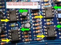
Perry Babin said:The 393 is a comparator that's run off of the 12 supply.
I wanted you to check the voltage on the audio op-amps (see attached photo). The audio op-amps are powered by the switching power supply.
ok all of the #4 pins were -15.25VDC the #8 pins were 14.75VDC
On AC you should read the same thing on the outer legs of one half of the outputs and on the center leg of the other half of the outputs. It's not really important. The power supply is operating (±63 volts told us that) and the amp is likely producing the square wave (150v AC).
The op-amps have the correct power supply voltage.
Measure the DC voltage across the speaker terminals (one meter lead on each speaker terminal). Do this with the amp on.
You said the amp was in protect. Is that still true?
The op-amps have the correct power supply voltage.
Measure the DC voltage across the speaker terminals (one meter lead on each speaker terminal). Do this with the amp on.
You said the amp was in protect. Is that still true?
Perry Babin said:On AC you should read the same thing on the outer legs of one half of the outputs and on the center leg of the other half of the outputs. It's not really important. The power supply is operating (±63 volts told us that) and the amp is likely producing the square wave (150v AC).
The op-amps have the correct power supply voltage.
Measure the DC voltage across the speaker terminals (one meter lead on each speaker terminal). Do this with the amp on.
You said the amp was in protect. Is that still true?
I got nothing on the speaker terminals
yes it is still in protect

This amp doesn't seem to be in protect. The transistor driving the LED may be defective. What happens if you connect a head unit to the inputs (do you get audio at the outputs)?
If you have the amp out of the heatsink, you shouldn't let it operate for more than a few seconds. Make all of the connections, then power it up.
If you have the amp out of the heatsink, you shouldn't let it operate for more than a few seconds. Make all of the connections, then power it up.
Perry Babin said:This amp doesn't seem to be in protect. The transistor driving the LED may be defective. What happens if you connect a head unit to the inputs (do you get audio at the outputs)?
If you have the amp out of the heatsink, you shouldn't let it operate for more than a few seconds. Make all of the connections, then power it up.
I hooked it up and got nothing -no audio no voltage
With the amp OFF and your meter set to ohms or diode check...
Find the common legs from the two pairs of output transistors. For 1/2 of the transistors, this will be the center leg. For the other half, it will be the third leg. These will be connected together and should be connected to the positve speaker terminal (the resistance from the common legs to the + speaker terminal should be ~0 ohms).
Do you have zero ohms from the common legs of the outputs to the positive speaker terminal?
Measure the DC voltage across the speaker terminals (one meter lead on each speaker terminal). Do this with the amp on.
This should be
connect the meter to the speaker terminals and then put ON the amp and observe if rising DC voltage is appearing at the speaker terminals.
If u measure with the amp ON, the protection has already kicked in and u will measure no voltage.
edit: repeat for all output channels as any or all will trigger the protection.
Gajanan Phadte
You should have started a new thread. Maybe a moderator will move these posts.
Have you emailed audiobahn to see if they would supply a replacement?
How bad is it?
They fail in different ways. If you're lucky, the only problem is that the enamel has been worn away and is causing an intermittant problem. In that case, you can unwrap it (generally only one turn) and insulate the winding with an insulating tape like kapton.
If the windings have shorted and some of the individual conductors have fused open, you could rewind it. Find some wire the same size as the individual strands and make up a bundle with the same number of conductors. Use a dial micrometer to determine the wire size of the individual conductors. Then unwrap the original windings carefully counting the number of turns used. Rewind the inductor with the new wire.
Perry Babin said:With the amp OFF and your meter set to ohms or diode check...
Find the common legs from the two pairs of output transistors. For 1/2 of the transistors, this will be the center leg. For the other half, it will be the third leg. These will be connected together and should be connected to the positve speaker terminal (the resistance from the common legs to the + speaker terminal should be ~0 ohms).
Do you have zero ohms from the common legs of the outputs to the positive speaker terminal?
It seems I have ~0 ohms on the center of half and the third of half to the positive terminal
should I also do the test described above? (for rising voltage)

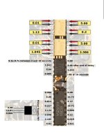
How does your amp compare to the voltages on the attached file?
This goes along with the photo:
The following voltages were taken after the turn-on delay. The B+ input voltage
was 13.01v. The
voltages for the various sections of the opto-couplers were taken 'across' the
terminals of the
opto-coupler (not referenced to ground). For voltages where times are given, the
times are
referenced to the time when the remote voltage was applied. For voltages where
there are no meter
probes shown, the black meter lead was connected to the chassis ground terminal
of the amplifier.
(I have added this from Perry Babin for the sake of the thread)
Attachments
gmphadte said:
This should be
connect the meter to the speaker terminals and then put ON the amp and observe if rising DC voltage is appearing at the speaker terminals.
If u measure with the amp ON, the protection has already kicked in and u will measure no voltage.
edit: repeat for all output channels as any or all will trigger the protection.
Gajanan Phadte
I followed your instructions and consistantly there was a momentary reading of .01 vdc then zero -you don't want DC to the speaker, right? It is a mono amp -only 1 output channel
Does it matter that I had no input signal?
- Status
- This old topic is closed. If you want to reopen this topic, contact a moderator using the "Report Post" button.
- Home
- General Interest
- Car Audio
- my first broken amp... need help