I don't have a 6CD6 tube here to curve trace, but the next best thing is a 6EX6, which is a modestly limit upgraded 6CD6. Looks like the 6EX6 has about half the plate knee voltages however (for better efficiency).
6CD6 datasheet:
http://tubedata.milbert.com/sheets/093/6/6CD6GA.pdf
6EX6 datasheet: (have never seen one with curves)
http://tubedata.milbert.com/sheets/106/6/6EX6.pdf
6CD6G was registered by RCA in 1949, 6CD6GA was registered by GE in 1954, and 6EX6 was registered by Raytheon in 1959.
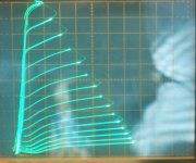
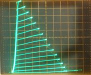
So some curves for the 6EX6:
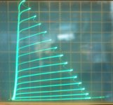
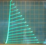
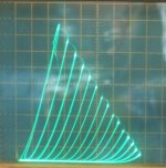
(50 mA/div Vert., 50V/div Horiz. for all)
1) 6EX6 normal pentode, g1 -2V steps down from 0, g2 at +150 V )
2) 6EX6 g2 drive, g1 at 0V, g2 +10.4V steps up from 0)
3) 6EX6 Twin/Crazy Drive, g2 +6V steps up from 0 V, Rg2g1 = 1560 Ohm, Rg2K = 2400 Ohm
4) 6EX6 Triode mode, g1 -6V steps down from 0)
6CD6 datasheet:
http://tubedata.milbert.com/sheets/093/6/6CD6GA.pdf
6EX6 datasheet: (have never seen one with curves)
http://tubedata.milbert.com/sheets/106/6/6EX6.pdf
6CD6G was registered by RCA in 1949, 6CD6GA was registered by GE in 1954, and 6EX6 was registered by Raytheon in 1959.
So some curves for the 6EX6:
(50 mA/div Vert., 50V/div Horiz. for all)
1) 6EX6 normal pentode, g1 -2V steps down from 0, g2 at +150 V )
2) 6EX6 g2 drive, g1 at 0V, g2 +10.4V steps up from 0)
3) 6EX6 Twin/Crazy Drive, g2 +6V steps up from 0 V, Rg2g1 = 1560 Ohm, Rg2K = 2400 Ohm
4) 6EX6 Triode mode, g1 -6V steps down from 0)
Attachments
Last edited:
I just noticed that the Twin/Crazy drive curve set I posted above (pic 3) for the 6EX6 was pulling the plate knees up to higher voltages. That's from too low an Rg2g1 resistor. (too much current into grid 1)
Here is an improved set with a higher (6K Ohm) Rg2g1, but somewhat less overall gm (+8 V steps instead of +6V steps before). (Rg1K still 2400 Ohm)
Improves the plate knee voltages and is safer for grid 1 operation (less than 2 mA max into grid1, about 7 mW peak power, 2 mW avg.). Plate knee voltages are comparable to g1 drive or to g2 drive now for efficient operation.
50 mA/div Vert., 50 V/div Horiz., 8 V steps, Rg2g1 = 6000, Rg1K = 2400
Attachments
Last edited:
great.
Smoking-Amp, I have followed your posts for years, since well before I registered here. That last thumbnail shows corners, not knees.
Now I am jonesing for 6EX6's. They look like nearly direct substitutions for the 6CD6's. The only way I will get relief is to go back to my favorite (and only) local electronics store, and search through tubs full of thousands of unsorted vacuum tubes to find 6EX6's. This is even though I have a cigar box full of 6CD6's. (The price for the 6EX6's will be right.) Since there are apparently no published curves, 6EX6's should not be picked over, yet.
Not quite as bad as it sounds. I bought a pair of driver boards from Tubelab. The boards take nine-pin sockets. I could adapt them to octal sockets for the 6N7's, but don't want to. Easier to find alternative tubes that match pinouts and performance.
I will find a couple of nine-pin twin-triodes to fit the purpose. They are there, just takes time and persistence, and frequent referrals to a tube data-sheet book. As long as I am there, I will search for the 6EX6's.
General Question for anyone with time to answer: time to confess to some blinding ignorance, in hope of enlightenment.
For my curve-fitting, I used the chart from the GE 6CD6-GA data sheet, dated, I believe, 12-54. I used the first chart on page 4.
I have become concerned that chart is for some kind of triode-strapped operation and not pentode operation, though it appears to vary grid 1 and screen grid voltages.
If I wanted to simulate 6CD6 pentode mode operation, should I have used one of the charts from page 5 instead? And if so, which one, and why?
I have been pretty much ignoring the cliff-like charts because they all compare PLATE voltage vs. plate current. I thought I wanted grid 1 voltage or screen voltage vs. plate current.
Now, Smoking-Amp is posting cliff-like thumbnails, and appears to be showing grid 1 and screen voltage vs. plate current.
What am I missing?
?...
3) 6EX6 Twin/Crazy Drive, g2 +6V steps up from 0 V, Rg2g1 = 1560 Ohm, Rg2K = 2400 Ohm
4) 6EX6 Triode mode, g1 -6V steps down from 0)
Is it Rg1K?
RE: Davorin
Good catch. A typo.
Should be Rg1K = 2400 Ohm
Value not real critical. Just a pull-down mostly.
---------------------
6EX6 I see listed at $5 at ESRC or Vacuumtubes.net
21EX6 I see listed at $3 at either.
A cheap 24V regulated DC power supply off Ebay, that can be adjusted down to 21V, would be a simple heater supply for 21EX6. (or 21LG6 or 21HB5 or 22KV6 or 24JE6 or 22KV6 all good tubes, or up a volt for 26DQ5)
----
The chart at the top of page 4 for the 6CD6 is showing the continuous effect of grid 1 voltage at a fixed plate voltage of +175 Volts. The stepping curves show the effect of different screen grid voltages. This is essentially a perpendicular slice (to the page) through the page 5 charts.
All are showing pentode operation.
Triode operation can be derived from the bottom page 5 chart by putting dots where screen voltage is equal to plate voltage. But only gives data for grid 1 = 0V.
.
Last edited:
Another thought on getting started here. Do you have experience with (what I consider) basic electronic test equipment? I mean a signal generator, DVM and a basic analog scope. If you have those items, especially a decent small scope, you'll have access to seeing things dynamically, and getting instant feedback on things like "does that waveform look right?", voltage offsets that you may not have expected to see and so on. Without a scope, you really have no way to clearly see what is going on in the circuit. And they are not too expensive these days, lots of used stuff on Ebay.
My first "good" build was a Steve Deckert design (Decware) using EL84 tubes as the outputs. I wanted to build it point to point for my own learning experience, and I was able to look at each stage as I completed it using the scope and a cheap signal generator that can put out audio frequency sine waves. I learned so much doing it this way, could get a gut feel very quickly of what works and what does not. And it worked!
Best of Luck,
Adam Reed
The 6CD6 page 5 top chart is the usual one used for plotting a load line. The screen grid chart below that normally would just tell you the minimum screen grid voltage required to reach maximum required load current on the load line. (ie, adjust power output, and also tube plate dissipation!) The top chart (page 5) is showing the plate currents for a specific screen grid voltage (and steppings for the grid 1 voltage). The whole chart current then can be scaled up or down according to the bottom chart for different screen grid voltage. The current gets scaled by the bottom screen grid chart, and the grid 1 step voltages also get scaled by the relative change to the nominal screen voltage (internal triode Mu effect between grid 1 and grid 2).
Twin/Crazy drive is an oddball here. It does use the bottom page 5 chart for screen grid voltage drive, like g2 drive schemes. But it also derives a grid 1 -current- drive to go along with that (through Rg2g1). Nothing on the datasheets to help much with that. Pretty much need a curve tracer to see what is going on, although one can model grid 1 as a thermionic diode. A current input to grid 1 then develops a non-linear (something like 2/3 power) grid 1 voltage to control cathode emission (in addition to the grid 2 V field drive). This is obviously a non-linear effect, but is how the Crazy drive is able to compensate the 3/2 power V to current of the grid 2 drive.
If you don't have a curve tracer (there is an inexpensive curve tracer kit online, the uTracer, but it may be challenged for power TV Sweep tubes, which can reach 1/2 an Amp plate current easily) you pretty much have to go by some selected operating conditions for the specific tube (Rg2g1 and Rg1K etc.)
You really should try out something simpler than Twin/Crazy Drive for your first project!
Get a good feel for how the standard grid 1 drive works first. Negative Grid 1 drive is high impedance, so a special power driver is not needed yet. Definitely get a working analog scope to see what is going on. One is nearly blind to electronics otherwise.
Then move up to positive grid 2 drive, which requires considerably more voltage (and current) than grid 1 drive. (power driver development)
Then it is an easy step over to Crazy drive from there (grid 2 AND grid 1 now positive territory). Just some resistors needed. But there are tricks involved with grid 2 and Crazy drive to get the tube to turn off fully. Plate resistance Rp (or Ri) has to be countered some by a modest negative drive voltage for cutoff (when plate V is really high).
.
Last edited:
Smoking-Amp, thank you for the observations. I will wrap my head around them. I did not understand those graphs to mean at all what you described.
Adam, thank you for your concern. One of the things I love about DIYAudio is the civility and sympathy posters get from more experienced folks, and the humility we see from the obviously wise.
I have a couple of oscilliscopes, a sine wave generator, an adjustable bench power supply, variacs, plus other useful stuff. I learned how to use the O'scopes in college, many years ago. I am experienced at chasing signals through circuits to find problems. Usually succeed but not always. My favorite is the blown fuse in some garage sale find.
I don't know if this experiment will succeed. I do know that I will have fun learning as I go.
Anything ever develop with this amplifier project?
I've been offline for most of the last year. Was just looking up a tube and found this thread in the search results.
Sounded like things were getting overly complicated when last discussed. It shouldn't be that hard to build a first tube amplifier if keeping to a simple design. Decide on the output tubes for the power level wanted, figure a practical OT. Work backwards thru the amplifier to figure the needs for previous stage(s). Or use Tubelab's or Millett's driver boards. Can always try out other approaches once you get the basics working.
A couple of bench supplies can make prototyping relatively straightforward.
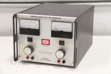
A Hoefer PS500XT supply for B+ (0 to 500, 0 to 400 mA, switching type supply) ($100 on Ebay) and either another Hoefer (there is also a Hoefer PS500 0 to 200 mA linear supply), or a Heathkit HV supply (IP-17, dang these things are priced out of sight lately on Ebay!!) for the screen supply, bias V and heater power.
I've been offline for most of the last year. Was just looking up a tube and found this thread in the search results.
Sounded like things were getting overly complicated when last discussed. It shouldn't be that hard to build a first tube amplifier if keeping to a simple design. Decide on the output tubes for the power level wanted, figure a practical OT. Work backwards thru the amplifier to figure the needs for previous stage(s). Or use Tubelab's or Millett's driver boards. Can always try out other approaches once you get the basics working.
A couple of bench supplies can make prototyping relatively straightforward.
A Hoefer PS500XT supply for B+ (0 to 500, 0 to 400 mA, switching type supply) ($100 on Ebay) and either another Hoefer (there is also a Hoefer PS500 0 to 200 mA linear supply), or a Heathkit HV supply (IP-17, dang these things are priced out of sight lately on Ebay!!) for the screen supply, bias V and heater power.
"Sounded like things were getting overly complicate" You make a good point. We all have different approaches to building amps but I think you can't beat soldering up a circuit on the bench, apply power and have a look at how it behaves, then go back and have a read of a datasheet or whatever.
I find it easier to bung stuff together even if not perfect rather than trying to figure it out on paper: it's easy to get lost.
"A couple of bench supplies can make prototyping relatively straightforward" Yes, but a HT/B+ tfmr, two diodes, a few caps and a few resistors and maybe a few batteries can do the same job
Andy.
Last edited:
Yes, but a HT/B+ tfmr, two diodes, a few caps and a few resistors and maybe a few batteries can do the same job
Sure, I would just add (for prototyping) a current limiter circuit for the screen grid(s) supply. Optionally also for the B+.
The bench supplies usually have that already built in. (the switchmode bench ones can also, Hoefer PS500XT, but are often a little slow to act/limit due to a big cap at the output)
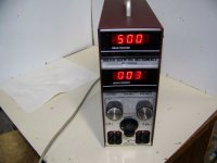
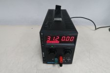
Surprising the Heath IP-17 is so expensive on Ebay, it doesn't have any limiting. The Hoefer PS 500 (no -XT) is a linear supply with limiting, good for a screen supply. Another is the Xantrex XT250-0.25, linear, to 250 V, and has fast limiting and digital V and I readeouts. All are in the $100 range except the Heathkit. ($250-$350 for a fix it up! Can forget those. I got a couple of the IP-17 supplies years back when they were just $35.00 )
Attachments
Last edited:
Anything ever develop with this amplifier project?
<snip>
Sounded like things were getting overly complicated when last discussed. It shouldn't be that hard to build a first tube amplifier if keeping to a simple design. Decide on the output tubes for the power level wanted, figure a practical OT. Work backwards thru the amplifier to figure the needs for previous stage(s). Or use Tubelab's or Millett's driver boards. Can always try out other approaches once you get the basics working.
A couple of bench supplies can make prototyping relatively straightforward.
A Hoefer PS500XT supply for B+ (0 to 500, 0 to 400 mA, switching type supply) ($100 on Ebay) and either another Hoefer (there is also a Hoefer PS500 0 to 200 mA linear supply), or a Heathkit HV supply (IP-17, dang these things are priced out of sight lately on Ebay!!) for the screen supply, bias V and heater power.
Dead stop since my last post. I picked up the whole thing again about a month ago. This project has been on-again, off-again for fifty years. Seems like I have to re-learn everything each time. The only benefit is, I get out of mental ruts when re-evaluating. Got side-tracked by trying to build a perfect electronics lab. Just recently I came across a receipt for parts for this project from 2000. Have settled on a pair of 6CD6's, a pair of TubeLab's universal driver boards, Dynakit Z-565 O/P transformers. Since TubeLab uses 6CG7's on his board (nominally), I changed to those instead of using 6N7's. (Not a typo, not "6SN7"). I will use a 120/240V step-down transformer that I already have as a step-up power supply. I need to pull together a B+ supply for the 6CG7's. Next step is to stage and label parts then solder together a breadboard and start smoking parts.
Aye, your right, can't beat a good bench supply, I have a huge 500v 5A beasty but they're not essential and not cheap as you say. I rarely use my bench PSU, often using a variac, iso tfmr, lamp limiter combo and cobbled together bits and bobs.
"This project has been on-again, off-again for fifty years" Blimey! I mucked about for two years on my first amp build and thought that a bit much... fifty years, strike a light : ) Good to see your still hanging on, try not to worry about stuff too much, bung it together for a first test and as mentioned a lamp limiter is a good idea as is a cap discharger when mucking about with high voltage.
6CG7's, good choice, 6N7's arn't the easiest of valves to use.
Good luck, Andy.
- Status
- This old topic is closed. If you want to reopen this topic, contact a moderator using the "Report Post" button.
- Home
- Amplifiers
- Tubes / Valves
- My Father’s Amplifier