Hello,
To be honest, in the past I hated ChipAmps. Until I discover the LM3886.
After lot of hours spent in researching, re-designing, testing and assembling, here is my final product. It is my version of famous Gainclone, with some improvements.
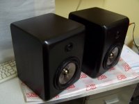
It is running with a pair of 2 way 4ohms speaker, 56WRMS for each channel.
Nice sound, punch bass, clear midrange, lowest distortion. I am happy with it.
I hope you like it and please give your comments about it.
Best Regards,
Julio Cesar.
To be honest, in the past I hated ChipAmps. Until I discover the LM3886.
After lot of hours spent in researching, re-designing, testing and assembling, here is my final product. It is my version of famous Gainclone, with some improvements.
It is running with a pair of 2 way 4ohms speaker, 56WRMS for each channel.
Nice sound, punch bass, clear midrange, lowest distortion. I am happy with it.
I hope you like it and please give your comments about it.
Best Regards,
Julio Cesar.
Attachments
3886 amp
you've used /included a power level ...from a tape player?.. perhaps I'm wrong. I also use parts from other pieces. Am curious how you did that. Nice amp- looks like a single power supply with two boards/channels. The three control knobs have me curious... My own efforts are so messy .. even with a picture no-one would be able to tell what is going where. thanks for putting it out here.
you've used /included a power level ...from a tape player?.. perhaps I'm wrong. I also use parts from other pieces. Am curious how you did that. Nice amp- looks like a single power supply with two boards/channels. The three control knobs have me curious... My own efforts are so messy .. even with a picture no-one would be able to tell what is going where. thanks for putting it out here.
")
Hi,
Thanks for your comments and interest.
Let's reply some of your questions:
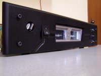
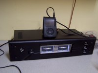
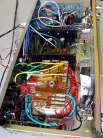
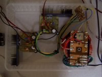
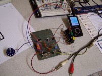
I have implemented a Preamp and 3 Band Baxandall EQ for this gainclone. So, I have the volume knob on left plus Lo / Mid /High knobs on the right side. This preamp / EQ section is based on TL072 (dual opmp) and is powered by an independent regulated symmetric power supply (+15 / -15Vdc).
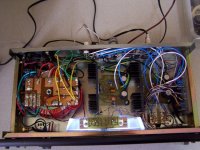
Then the signal goes to the poweramp section that is based on the LM3886 powered with symmetric power supply independent (only for power section) (+32 / -32Vdc without load).
Note: The complete unit is stereo, but I have 1 power supply common for the 2 preamps / EQ section and 1 power supply common for the 2 LM3886 section.
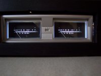
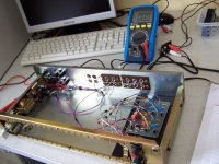
The audio output from LM3886 goes to full wave germanium diodes and then to the VU Meters, that are microamperimeter that I got from an old Tape Deck. The backlight is 2 white LEDs.
The heatsinks are inside the case and there is no any fan or forced vent (I hate this kind of stuff, due to noise and dust accumulation). There is a small vent grid on the top of case cover. Until now, I have not had overheating problems.
The case and chassis I recycled from an old Stereo 10 Band EQ. I removed all the electronic boards and all the 20 sliders potentiometers and the front panel.
The front panel (facial) I had to make from a piece of MDF. Actually, this piece of MDF was a small door from a kitchen cabinet.
I cutt it and worked on it, drilling, sanding and finishing. Then I applied a final black paint for a good look.
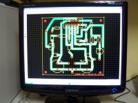
I will share the schematics here, I am just editing it on the Circuitmaker sch editor. I soon as I finish it I will post here, with complete information. I will also show some results of my experiences with it.
I am enjoying this sound system, and it seems to be one of the best I have heard till now. It does not fatigue my ears. And the EQs are so musical.
By the way, below is a pic of my speakers that I am using with this project. I also hand made it, and I used a car kit speaker. The tweeters are neodimiun. It has a bass reflex (on the rear).
Thanks for your comments and interest.
Let's reply some of your questions:
I have implemented a Preamp and 3 Band Baxandall EQ for this gainclone. So, I have the volume knob on left plus Lo / Mid /High knobs on the right side. This preamp / EQ section is based on TL072 (dual opmp) and is powered by an independent regulated symmetric power supply (+15 / -15Vdc).
Then the signal goes to the poweramp section that is based on the LM3886 powered with symmetric power supply independent (only for power section) (+32 / -32Vdc without load).
Note: The complete unit is stereo, but I have 1 power supply common for the 2 preamps / EQ section and 1 power supply common for the 2 LM3886 section.
The audio output from LM3886 goes to full wave germanium diodes and then to the VU Meters, that are microamperimeter that I got from an old Tape Deck. The backlight is 2 white LEDs.
The heatsinks are inside the case and there is no any fan or forced vent (I hate this kind of stuff, due to noise and dust accumulation). There is a small vent grid on the top of case cover. Until now, I have not had overheating problems.
The case and chassis I recycled from an old Stereo 10 Band EQ. I removed all the electronic boards and all the 20 sliders potentiometers and the front panel.
The front panel (facial) I had to make from a piece of MDF. Actually, this piece of MDF was a small door from a kitchen cabinet.
I cutt it and worked on it, drilling, sanding and finishing. Then I applied a final black paint for a good look.
I will share the schematics here, I am just editing it on the Circuitmaker sch editor. I soon as I finish it I will post here, with complete information. I will also show some results of my experiences with it.
I am enjoying this sound system, and it seems to be one of the best I have heard till now. It does not fatigue my ears. And the EQs are so musical.
By the way, below is a pic of my speakers that I am using with this project. I also hand made it, and I used a car kit speaker. The tweeters are neodimiun. It has a bass reflex (on the rear).
Attachments
Very Nice Work,
I like the use of the 3 ch EQ the only thing I would do differently is implement an EQ bypass switch, for a direct from source input! (but that would be to suit my need's rather than yours).
I have done somthing simular in the past with the VU meters only they were the LED style VU's I got from an old tape deck.
Well Done!
- Status
- This old topic is closed. If you want to reopen this topic, contact a moderator using the "Report Post" button.
- Home
- Amplifiers
- Chip Amps
- My DYI GainClone finished - Nice sound!