It seems Sevy found the bad connection in post 57 (plausible explanation for the sudden jump in noise earlier in the thread while he watched TV), with the remaining noise coupling in on the left channel as it runs past the AC line.Sizzle noise is usually from a bad component, bad connection, or else from AC line noise.
While cross-referencing to find the origin of this amp, I found your Facebook page and therefore found the origin of this amp.Sevy in a mirror!
Yes that's me. Why?
You started from a Cordel diagram and you seem to know what you are doing.
Where I don't have any information is on the design of the PCB, I am not capable of designing one myself, but over the years, I have assembled many amps and other devices which were from a "first draft" and each time I had strange behavior like your amp does, it was due to a problem with the layout or sizing of the tracks.
So to summarize, I am a troubleshooter, not a designer but I have a lot of experience in "assembly" and debugging and I come to my final question, have you done a "blank" assembly outside the box, scattered on the table before moving on to the final edit? and if so, have you already had this problem?
If you have nothing plugged into your amplifier and it hums or has noise, you probably have a common impedance coupling problem somewhere in the wiring or on the PCB layout. Since you do not have this, it is likely that aspect of the amp is all ok. If you next do the cross-channel loop test as you did above, and the amp is quiet to your satisfaction, then it is probable you do not have anything wrong with the internal wiring and routing (BTW, do not forget to rotate the transformer +-60 degrees - often you can get a substantial reduction in hum). If you now connect your source gear, and it hums, it's likely you have a classic inter-equipment ground loop or a hum problem in your source gear.
To check for the probable source, connect to your preamp, but keep the preamp turned off, but plugged into the wall with the wall switch OFF.
If it hums, you have a ground loop through the ground cabling that goes from your power amp ground to the wall socket, through the ground connection between the preamp and power amp wall sockets, out to your preamp, through to the preamp signal ground and then through the interconnect cable signal returns back into the power amp.
Does the level of hum change if you move the mains and/or interconnect cabling? If yes, the hum is from AC mag fields cutting the interconnect wiring loops and inducing an EMF in the ground and/or signal returns. In this case, a ground lifter or dressing the external wiring can help.
If it does not hum with the source equipment wall switch OFF, but hums when you turn it ON, you have a noise problem in your source.
It is quite normal to have these kinds of problems stacked one on top of the other - so a common impedance problem, a cross channel ground loop and then an AC ground loop. You just have to go through some logical steps to isolate the issues one by one.
Here are some slides to help with this:-
Last edited:
If you mean having the Amplifier PCB assembled on it's heat-sink, flat on the test bench; yes I did that. But the Input connector wasn't shield at all in this setup and was picking a lot of noises, until I plugged the headphone at the output and minimize the noise by touching the ground of the headphone female connector. This was because my body was acting as the ground path to earth.I come to my final question, have you done a "blank" assembly outside the box, scattered on the table before moving on to the final edit? and if so, have you already had this problem?
If you are curious and have time to read (with a coffee or a bear, depending of your taste), then you can follow the full history of my adventure in these chronological links:
https://www.diyaudio.com/community/threads/looking-for-amp-camp-amp-chassis-dimensions.401791
https://www.diyaudio.com/community/...nce-hyrid-mosfet-audio-power-amplifier.404839
https://www.diyaudio.com/community/threads/a-lateral-mosfet-power-amplifier-design-second-try.405651
Then, this actual thread ;-)
Have fun!

Already did that ;-)BTW, do not forget to rotate the transformer +-60 degrees - often you can get a substantial reduction in hum
Agreed... This morning after waking up, I stay right in front of the gears rack and powered on the Monster Reference Power Center HTS-5000. It is programmed to power on the Power Amplifier 40 seconds after all the sources gears are on. Then I waited for the speakers protection relays to engages, about 2 seconds.If you now connect your source gear, and it hums, it's likely you have a classic inter-equipment ground loop or a hum problem in your source gear.
Once done, I was not able to hear any noise from my position compared to before the relays engages...
So in resume, I would say that the hum is very quiet and acceptable. But it is when I compared it with the Rotel, with my ear close to the speakers, that I want to obtain the total silence Nirvana ;-)
So I keep learning and trying...
Following your suggestions above, with the Technics pre-amplifier still connected to the AC plug but with it's power at Off, I get the same results.
Knowing that the TV is the worse source as I can easily hear a buzz when I turned it On while it's output level is to low, I tried to disconnect it from it's own Power Bar on a separate wall of the audio gears, and also disconnected it's audio cables at the pre-amplifier. I still get the same results, so I am sure the TV is not the culprit.
All my DIY Amplifier, the Rotel Amplifier and the Revox PR99 are AC plugged into the same Power Bar. This latest is then connected into the Main Amp socket of the Power Center HTS-5000, like this:
Then I tried to connect the DIY Amplifier directly into the Power Center HTS-5000 Main Amp. socket. I noticed absolutely no change with this setup. So this should disregard also the AC Power Bar used for the Amplifiers and the tape deck.
Then I played with the configuration of the RCA interconnect cables as you suggested. In the original setup and all previous tests, the cables were simply pending like this (with Green shadows) :
Then I passed them like this:
With this configuration, the right channel (ENTRÉE DROITE) became totally quiet! I cannot noticed a difference by ear on the left channel. I am pretty sure that the path of the left channel that has no choice to go close to the AC socket inside the case is the culprit of the residual noise on my left channel...
This would be difficult to test as my Power Supply integrate both Speakers Protection Relays and circuit. I could of course remove the power from one amplifier board, but only the left channel is picking noise, and it surely not picking it from the quiet right channel!Have you isolated one channel, ie removed power, to see if the problem persists?
I had a similar problem and going to separate power supplies made a significant improvement.
See posts #25 and #59Does your power socket also have a mains filter or is it just a power socket?
?? I don't understand your suggestion? Plugging the two main red wires of the toroidal transformer directly to one main output socket of the Monster Reference HTS-5000 with an AC cable? Without any lines protections fuses?!Do you want to try without the main/filter socket ,directly from the Monster ?.
I don't think so...
One test I never shared in this thread is this one: while seeking the noise source with the headphone on my head, in the very beginning of the construction setup, when at that time the Input connectors of the Amplifier PCB were oriented in the back of the case, I could ear a very loud noise. I took out the AC socket from it's back panel and put it far away from the Input connectors, in direction of the front of the case. This test was very conclusive that the AC socket was the source of the noise. That is the reason why I inverted the orientation of both boards, in the goal to put the Input PCB connectors as far as I could from the AC socket. But the left channel Input connector is still to close to the AC socket and wiring it's path to reach the Input connector of the Amplifier board could not be done without crossing the AC socket. Unfortunately, the hole of this AC socket is now made and unless I buy another rear panel and redo the job, I guess I will have to live with the left channel residual noise, that I must admit is really low and acceptable, totally imperceptible when you are sited down in front of the whole system listening music.
No .?? I don't understand your suggestion? Plugging the two main red wires of the toroidal transformer directly to one main output socket of the Monster Reference HTS-5000 with an AC cable? Without any lines protections fuses?!
With an IEC base which integrates a fuse, just to test.
You mean without a filter?With an IEC base which integrates a fuse, just to test.
I don't have access to an IEC without filter. Mine have one...
False!!!I don't have access to an IEC without filter. Mine have one...
I was making a bicycle ride and remembered one of my backups tube preamplifier that has one...
I loose nothing to try ;-)
With an IEC base which integrates a fuse, just to test.
Good guest but, no better result lol...
Without anything connected to the Input, quiet silent on both channels. With a RCA loop cable, tiny low volume, almost imperceptible noise on both channels. This test was better with the IEC Filter/Fuse socket, with almost total silent on both channels, lower then a fly!
With the pre-amplifier gears connects, same as with the RCA loop cable. This test was better with the IEC Filter/Fuse socket, with total silent on the right channel but tiny low volume, almost imperceptible noise on left channel...
Thank for your suggestion, it was worth to try it ;-)
I asedk modushop,biz for the possibility to send a new aluminum rear panel with holes based on my specifications. They can do it. So my next upgrade would be to buy new RCA connectors with better quality, I like the Tiffany style, and redo the back panel setup with both RCA connectors close to each others, the speakers posts in the same place and the AC IEC Socket far from the Amplifier PCB. That would be the best I could make for further improvement, I guess...
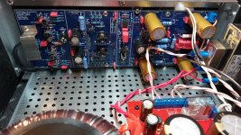
My AC socket/filter has a metal case, I'd suggest that if it's not shielded then the inductors in it may radiate stuff. If you can't get a metal cased one, perhaps you can put some shielding around it somehow?I took out the AC socket from it's back panel and put it far away from the Input connectors, in direction of the front of the case. This test was very conclusive that the AC socket was the source of the noise
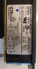
If you have a close look at the first picture below, you'll notice that it is already shielded. Also in the second picture I show the schematic of the filter from the sticker on it.I'd suggest that if it's not shielded then the inductors in it may radiate stuff.
Attachments
Unfortunately, Randy Sloan is no longer with us, so he is unable to explain why he suggested this. In general, for the lowest distortion and noise, you should run the speaker return back to the amp module and then from the amp module back to the PSU. You have a few radiating loops here - the V+ and the V- with the speaker connections and then the 0V with the V+ and V- power supply. For this reason, you want to keep all the loop areas as small as possible and must therefore twist the V+, V- and 0V tightly together. The speaker out from the amp, along with the speaker return from the amp module out to the speaker connectors on the back of your amp must be tightly twisted together. If you follow this approach, the radiated noise from the cabling will be minimized. This same approach applies to the power supply wires from your transformer to the rectifier and soothing caps, and then to the amplifier module - twist the cables tightly. Also, the same on the transformer's primary side. If you get this right - and assuming the PCB layout is well done - you should get about -120 dBr ref full output or < -95dBV with the inputs shorted. These levels of noise should be completely inaudible to a young listener with their ear in the speaker cone.Quick question to Bonsai...
I have finished to read your presentation document. In my very first wiring setup I twisted the three cables +50VDC/GND/-50VDC with gauge 16 wires. Then I read back a comment in my book "High-Power Audio Amplifier Construction Manual" from G. Randy Slone;
I quote:
So I choose to redo my wiring, this time only twisting the +50VDC and -50 VDC together, while laying the ground wires on their own under the aluminum plate that serve to fix the transformer and the Power Supply PCB.
Seeing that untwisting the three wires from the first wiring setup have damage the jacket of the wires, I had to order new cables to redo the new setup.
Now I am reading from your document, at page 19, that the First Line Remedy is, and I quote:
So I am confuse. Should I twist all three wires together or just the +50/-50 VDC ?
Do you have a picture of the internals of your amp from above with the wires labelled?
- Home
- Amplifiers
- Solid State
- My DIY Amplifier has a small sizzling sound