
Hi Alex,The output can be configured as ground sensing (see above) or as balanced (meaning hot and cold outputs with equal impedances, not two signals with opposite phase)
I'm looking for a line driver for the Zeus amp. It should be able to drive the 600 ohm input transformer.
https://www.diyaudio.com/community/threads/zero-feedback-impedance-amplifiers.42259/post-488194
Current configuration with balanced DAC output 100ohm to the transformer doens't work. 100ohm seems too much.
1. You state "not two signals with opposite phase". Guess that's a problem?
2. Is the output impedance low enough?
I'd prefer to keep everything balanced from in to output so I would hope this driver could do the trick?
Hugo
Driving the Zeus with a bunch of opamps?
1. Unlike some BTL amps, a transformer's primary does not need two opposite-phase signals; one is enough.
2. In the stock schematic, the balanced output impedance is 44 ohm - it is just two resistors 22 ohm each:

The output impedance of the opamp is effectively zero thanks to NFB. R17 decouples the opamp from possible capacitive loads (e.g. cables) that otherwise might affect stability. R18 provides an impedance on the "cold" wire identical to that on the "hot", which helps the common mode rejection of the downstream device.
Transformers generally like being driven by low (or even negative) impedance sources, both for distortion and for the flatness of frequency response reasons. You can reduce R17/R18 as long as the opamp remains stable with the load, including when clipping and on fast transients. I think it should be easy to make it work.
But what doesn't work with just the trafo?
1. Unlike some BTL amps, a transformer's primary does not need two opposite-phase signals; one is enough.
2. In the stock schematic, the balanced output impedance is 44 ohm - it is just two resistors 22 ohm each:
The output impedance of the opamp is effectively zero thanks to NFB. R17 decouples the opamp from possible capacitive loads (e.g. cables) that otherwise might affect stability. R18 provides an impedance on the "cold" wire identical to that on the "hot", which helps the common mode rejection of the downstream device.
Transformers generally like being driven by low (or even negative) impedance sources, both for distortion and for the flatness of frequency response reasons. You can reduce R17/R18 as long as the opamp remains stable with the load, including when clipping and on fast transients. I think it should be easy to make it work.
But what doesn't work with just the trafo?
Let me see if I understand the design goal here. You've reduced the already well below audible THD by an additional 0.00028% over a THAT1206, but have thrown away 37dB of CMRR to do it? Are you aware that the main, and only point of balanced transmission is common mode rejection? You may never run into this in smaller installations, but in a studio, 53dB of CMRR is NOT adequate. I question the validity of the trade-off.
I think that is bit harsh, and while true - have you looked at the typical op-amp based balanced input circuit? A lot of them came with 1% tolerance resistors and achieved consideably less than 40dB CMRR - enough to still be useful in a lot of instances. I like the ThatCorp balanced drivers and receivers and have used the 1206 and others in my designs in the past. (I am not doing much audio design these days.)
Likely careful matching of all of the complementary resistors in the balanced input circuit would improve the CMRR. The lack of input capacitors is a nice feature as long as input current is limited by suitable means if the input is driven with no power present.
Likely careful matching of all of the complementary resistors in the balanced input circuit would improve the CMRR. The lack of input capacitors is a nice feature as long as input current is limited by suitable means if the input is driven with no power present.
Last edited:
I've built many. One "trick" is not to use individual resistors, but use a laser-trimmed R-pack. The total resistance value might be 1%, but section to section match is far better. But the monolithic solutions exist because this has always been an issue, and have existed since the PMI/SSM days. There simply no need to try to roll your own.
Harsh as it may seem, the one purpose to balancing is CMRR. Otherwise, it's not a thermal noise advantage, and never has been. If you want the cleanest interface, unbalanced is the solution. If you don't need CMRR in the first place, unbalanced will out-perform any pair of balanced interface devices. Always. And for short, like 1-2 meter interconnects, unbalanced works just fine.
Harsh as it may seem, the one purpose to balancing is CMRR. Otherwise, it's not a thermal noise advantage, and never has been. If you want the cleanest interface, unbalanced is the solution. If you don't need CMRR in the first place, unbalanced will out-perform any pair of balanced interface devices. Always. And for short, like 1-2 meter interconnects, unbalanced works just fine.
@jaddie: first you need a better CMRR, then in the next post, an unbalanced connection with zero CMRR works fine for you. It would be interesting to look at one of your builds as an example and see what choices you made and why, and what outcomes that brought about. Are there any measurement you could share?
In any case, this is a topic I'd like to explore deeper, and on which I very much welcome opinions, so I am happy you raised the issue. But let me unpack it a little.
First, a "well below audible THD" not inaudible. I learned it while debugging some power and headphone amps with ultra low, as in below -140dBc, THD (of which Omicron has been published on this forum). An SPL calculation tells you that either way, the distortion products are below the auditory threshold, yet you can clearly hear the difference. Don't take my word for it, build a copy of Omicron on a solderless breadboard and hear for yourself. Or look at @tomchr's Modulus series of amplifiers. Tom used THAT1200 initially but designed it out (see e.g. here, here, or here) in later versions.
Second, as @kevinkr pointed out, the CMRR at lower frequencies largely depends on resistor matching. The measurements above were taken on a board with 1% resistors. I feel that -53dB is quite good compared to what can be achieved with a single ended connection and e.g. a ground loop breaking resistor aka GLBR. Still, choosing resistors with a tighter tolerance is an easy fix. Out of curiosity, I built one board with 0.1% resistors, and the results were, predictably, about an order of magnitude better:


If one wants to go extreme, matched resistor networks such as the LT5400, are available, but IMO it would be an overkill for a line level DIY audio project.
Third, the CMRR at higher frequencies depends on matching not only the resistors but also the input EMI filter parts, including capacitors. Bill Whitlock is super clear on this is his patent underlying THAT1200:

THAT1200 and other line receiver ICs benefit from matched resistors on the chip, but the EMI filter is still discrete, and I wish anyone luck finding capacitors with better that 1% tolerance. With that in mind, I would be interested to see a CMRR vs frequency chart (like one above) for a good piece of studio equipment.
Fourth and most practical, THAT1200's CMRR is supposed to really shine with mismatched hot and cold source impedances. THAT Corp. calls it InGenius, but it is just bootstrapping that raises the common mode input impedance. (I use a humble high value resistor for that purpose.) I feel that this feature is a bit overrated. In a studio environment, I imagine one can expect balanced outputs with reasonably matched hot and cold impedances, so a superior ability to ignore an impedance mismatch has little practical significance. In a home system, where single ended sources are common, as @jaddie mentioned, one may never run into an issue because the installation is small. Do you think this feature is needed. desirable, and worth of additional complexity?
In any case, this is a topic I'd like to explore deeper, and on which I very much welcome opinions, so I am happy you raised the issue. But let me unpack it a little.
First, a "well below audible THD" not inaudible. I learned it while debugging some power and headphone amps with ultra low, as in below -140dBc, THD (of which Omicron has been published on this forum). An SPL calculation tells you that either way, the distortion products are below the auditory threshold, yet you can clearly hear the difference. Don't take my word for it, build a copy of Omicron on a solderless breadboard and hear for yourself. Or look at @tomchr's Modulus series of amplifiers. Tom used THAT1200 initially but designed it out (see e.g. here, here, or here) in later versions.
Second, as @kevinkr pointed out, the CMRR at lower frequencies largely depends on resistor matching. The measurements above were taken on a board with 1% resistors. I feel that -53dB is quite good compared to what can be achieved with a single ended connection and e.g. a ground loop breaking resistor aka GLBR. Still, choosing resistors with a tighter tolerance is an easy fix. Out of curiosity, I built one board with 0.1% resistors, and the results were, predictably, about an order of magnitude better:
If one wants to go extreme, matched resistor networks such as the LT5400, are available, but IMO it would be an overkill for a line level DIY audio project.
Third, the CMRR at higher frequencies depends on matching not only the resistors but also the input EMI filter parts, including capacitors. Bill Whitlock is super clear on this is his patent underlying THAT1200:
THAT1200 and other line receiver ICs benefit from matched resistors on the chip, but the EMI filter is still discrete, and I wish anyone luck finding capacitors with better that 1% tolerance. With that in mind, I would be interested to see a CMRR vs frequency chart (like one above) for a good piece of studio equipment.
Fourth and most practical, THAT1200's CMRR is supposed to really shine with mismatched hot and cold source impedances. THAT Corp. calls it InGenius, but it is just bootstrapping that raises the common mode input impedance. (I use a humble high value resistor for that purpose.) I feel that this feature is a bit overrated. In a studio environment, I imagine one can expect balanced outputs with reasonably matched hot and cold impedances, so a superior ability to ignore an impedance mismatch has little practical significance. In a home system, where single ended sources are common, as @jaddie mentioned, one may never run into an issue because the installation is small. Do you think this feature is needed. desirable, and worth of additional complexity?
I explained why high CMRR is necessary, AND why in some cases, no CMRR is necessary. Did you miss the exmplanation?
First point: THD at these figures is not audible. You might be confusing some other audible property, but harmonic distortion at any of those figures is not audible. But this gets into a discussion of test signals, test methodology, and bias management that we might not want to do here. But assuming the application is music, there are no music signals that permit audibility of these levels of distortion, and none that haven't already be far more distorted along the way to release. Masking swamps harmonics. Again...another discussion.
Second point: Yes, resistor match is the problem, and that's why you don't build it with 1% resistors. -53dB CMRR is NOT adequate for professional applications. Absolutely not. Haven't you looked at resistor arrays? Is a 0.05% section match interesting?
Here's one example:
https://www.digikey.com/en/htmldatasheets/production/9832041/0/0/1/tdpt16032002auf
But why bother when the monolithic solution is already better...and done?
You might, or might not need EMI filtering, it's application specific.
My point is, you don't need ANY CMRR in small systems with interconnects 1-2 meters, and with proper system grounding. You just don't. But if you're building large systems, studios, etc., CMRR becomes essential very quickly. You might feel the THAT1200 series is "over-rated", but it's used by the 1000s in huge numbers of professional systems. You're already listening to dozens of them in series.
Any CMRR is better than no CMRR. I agree there. I'm surprised you're not seeing better than about 50 dB CMRR even with ±1% resistors, though. I wonder if the DC servo is mucking things up for you.I feel that -53dB is quite good compared to what can be achieved with a single ended connection and e.g. a ground loop breaking resistor aka GLBR. Still, choosing resistors with a tighter tolerance is an easy fix. Out of curiosity, I built one board with 0.1% resistors, and the results were, predictably, about an order of magnitude better:
I do understand that 40 dB is the best you can guarantee with ±1% matching, but I've always found the matching of four resistors on the same tape to be much tighter than ±1% - at least as judged by the CMRR of the implemented differential receiver. I don't recall seeing a big improvement going from 1% to 0.1% resistors. The main reason I specify 0.1% resistors in critical places is so that it can't come back to bite me later.
I'm not sure where in Whitlock's patent(s) your snippet came from. I'm thinking it's from the prior art section of the patent. I think we can all agree that good matching of the impedances in the differential receiver is key for good CMRR. At least if these impedances influence the gain of the circuit. I think you may be missing the central part of Whitlock's patent, however: The common-mode bootstrap is where the secret sauce lies. That's the invention. That's how the THAT1200 achieves such good CMRR across frequency. The on-die resistor matching helps too, but unless THAT Corp uses a semiconductor process optimized for analog electronics (which they probably do) the resistor matching on die won't be any better than what you could do with discrete components and careful circuit layout.
Kudos to you for measuring your circuits, though. I appreciate that. Too many rely exclusively on simulations and forget to check their work. Keep it up!
Tom
The only real issue with the THAT InGenius devices is noise. The driver (1646) is -101dBu and the corresponding (1200 series) receiver is around -106dBu.
You can do a whole lot better than that with opamps (around -120dBu), but lose the superb CMRR of the THAT units. As Tom says you end up in the territory of matched or tight tolerance resistors with low or matched tempco, or tight tolerance resistor networks (although most or all of these seem to be thick film - not the best technology for audio).
Craig
Just noticed the link in Jaddie's post to Vishay/Dale thin film resistor networks. I'd previously only found thick film networks. Thanks for the link!
I've used the Vishay thin film networks, and ones from Texas Components in semiconductor ATE hardware designs and found them to be excellent, but expensive enough that I have used them only once in a DIY project. (Balanced inputs and highly accurate attenuators)
Since there has been some questions on the availability of these boards. I am starting a group buy to see if there is enough interest to warrant a manufacturing run. If interested, please sign up. The group buy will close on Saturday, September 30, so be sure to sign up soon.
Last edited:
Interesting exercise, but you are aware that many popular tweeters have H2 of only -30 dB H2, perhaps even as "bad" as -25 dB H2, at the low end of their passband?Let me conduct a little experiment. Let's say we have an amplifier that adds 0.01% of the 2nd harmonic (H2) and 0.001% of the 3rd (H3):
View attachment 1203366
The distortion is not particularly high and is all low order, harmonious and benign, perhaps even euphonic.
Now let me play a simple chord, A-C#-E:
View attachment 1203368
Oops. In addition to H2 and H3, our benign test amplifier sputters a bunch of intermodulation products, musically unrelated to the chord, with levels comparable or in some cases above those of H2 and H3. These are not euphonic and would not be masked by music. Such an amplifier might be ok for simple music such as a solo vocal, but would get confused with anything moderately complex, and would mush a full orchestra.
So, while various components of the audio chain undoubtedly distort, 0.01% THD does not give your amplifier transparency, and you do get audible benefits from making one of them more linear.
The part list a.k.a. BOM for one balanced line receiver board (see post #6 for the schematic and board outline):
With the part numbers shown in the right column and today's prices on Mouser.com, the total cost of this BOM with 1% 1kOhm resistors is just shy of $11.
Just a reminder: the GB for these boards is closing tomorrow.
| Qty | Value | Device | Package | Names | Example P/N |
|---|---|---|---|---|---|
| 2 | LM4562 | Dual opamp | DIP8 | U1, U2 | LM4562NA/NOPB |
| 1 | 2M2 | Metal film resistor | Axial 0204 | R1 | MFR-12FTF52-2M2 |
| 2 | 47k | Metal film resistor | Axial 0204 | R2, R3 | MFR-12FTF52-47k |
| 2 | 12k | Metal film resistor | Axial 0204 | R4, R5 | MFR-12FTF52-12k |
| 4 | 1k | Precision metal film resistor | Axial 0204 | R6, R7, R14, R15/R16 | MFR-12FTF52-1k (1%) or CMF501K0000BEEB (0.1%) |
| 4 | 10k | Metal film resistor | Axial 0204 | R8, R9, R12, R13 | MFR-12FTF52-10k |
| 2 | 220k | Metal film resistor | Axial 0204 | R10, R11 | MFR-12FTF52-220k |
| 2 | 22R | Metal film resistor | Axial 0204 | R17, R18 | MFR-12FTF52-22R |
| 2 | 100R | Metal film resistor | Axial 0204 | R19, R20 | MFR-12FTF52-100R |
| 4 | 47u | Electrolytic capacitor | Radial D=5mm | C1, C2, C3, C4 | EEU-FC1C470B |
| 2 | 470p | NP0/C0G ceramic capacitor | Radial LS=5mm | C5, C6 | FG28C0G1H471JNT06 |
| 4 | 10u | Non-polar electrolytic capacitor | Radial LS=5mm | C7, C8, C9, C10 | ECE-A1VN100U |
With the part numbers shown in the right column and today's prices on Mouser.com, the total cost of this BOM with 1% 1kOhm resistors is just shy of $11.
Just a reminder: the GB for these boards is closing tomorrow.
Hi Alex,
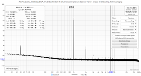
I'm enclosing measurement results obtained with your PCB in two configurations: 2xLM4562 and OPA1656/OPA2156.
The measurement setup consisted of the Victor's oscillator with a 1656 parallel buffer, Hall topology notch filter (Groner PCB), Groner's 60dB LNA (0.39nV/rtHz) and a Cosmos ADC. The PSU was Jan Diddens's SilentSwitcher, itself supplied by a Power Bank.
The filter represents a load of about 1.8k, so at an output voltage of 2Vrms my measurement results should be comparable to yours at the first page of this thread.
The first measurement, made with 2xLM4562 on the PCB, produced the 2nd at -135dBc (-85.5 - 50 for the filter attenuation), which is the same as you obtained. The 3rd is at -158 in my case, some 18dB lower than your result.
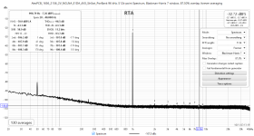
The combination of OPA1656 at the input and OPA2156 as the diff. stage resulted in excellent figures for the 2nd and 3rd harmonics: -156 and -162dBc, respectively. Since the harmonics were just visible with the arithmetic averaging in REW, I had to resort to the coherent averaging (s. the 2nd att).
Now I'm fully aware of the fact that at these distortion levels I must take the results obtained with a grain of salt, but since TI measured the 2nd and 3rd harmonics of less than -160dBc at Vout of 3Vrms (s. Fig. 12 in the OPA1656 DS), the figures I obtained are at least not impossible.
It's a nice PCB you designed, Alex!
I'm enclosing measurement results obtained with your PCB in two configurations: 2xLM4562 and OPA1656/OPA2156.
The measurement setup consisted of the Victor's oscillator with a 1656 parallel buffer, Hall topology notch filter (Groner PCB), Groner's 60dB LNA (0.39nV/rtHz) and a Cosmos ADC. The PSU was Jan Diddens's SilentSwitcher, itself supplied by a Power Bank.
The filter represents a load of about 1.8k, so at an output voltage of 2Vrms my measurement results should be comparable to yours at the first page of this thread.
The first measurement, made with 2xLM4562 on the PCB, produced the 2nd at -135dBc (-85.5 - 50 for the filter attenuation), which is the same as you obtained. The 3rd is at -158 in my case, some 18dB lower than your result.
The combination of OPA1656 at the input and OPA2156 as the diff. stage resulted in excellent figures for the 2nd and 3rd harmonics: -156 and -162dBc, respectively. Since the harmonics were just visible with the arithmetic averaging in REW, I had to resort to the coherent averaging (s. the 2nd att).
Now I'm fully aware of the fact that at these distortion levels I must take the results obtained with a grain of salt, but since TI measured the 2nd and 3rd harmonics of less than -160dBc at Vout of 3Vrms (s. Fig. 12 in the OPA1656 DS), the figures I obtained are at least not impossible.
It's a nice PCB you designed, Alex!
Attachments
- Home
- Source & Line
- Analog Line Level
- My Balanced Line Receiver