Simply is best! With less chips to get better performance is needed.
I think you're missing the whole point of this design.
Simply is best! With less chips to get better performance is needed.
And why do you think that is true?
Hi :
I tried to google it, but I can't find any post why Mauro decided to put the protection relay on the ground side. Is there any advantage on doing so? Most protection circuits I find put the relay on the HOT side. Is it okay to move the relay contacts to the HOT side?
Currently, it is possible to bypass the protection relay even accidentally without the operator's knowledge (depending on the overall grounding scheme).
I wouldn,t use SS relays for speaker protection though. they arent entirely linear.
not only that, but a serious fault in a amplifier could actually result in the same fault being created in the SS relay as well, (they are only just back to back mosfets), and thus wouldnt even disconnect the relay.
To me, SS relays have their places thats for sure, Soft start for example. But for high current low voltage dc for things that MUST absolutely be disconnected, a nice fat 12 volt relay with nice big contacts for me is a personal preference.
That and the clunk sounds so satisfying.
[OT] my own amp has 10 different relays for various functions controlled by arduino. they are all sequenced and sound great. They seem to tickle my brain in a good way. [OT]
read the recent Threads on SS relays for a very different opinion with experimental reports on performance.I wouldn,t use SS relays for speaker protection............................. But for high current low voltage dc for things that MUST absolutely be disconnected, a nice fat 12 volt relay with nice big contacts for me is a personal preference.
That and the clunk sounds so satisfying..................
Rainwulf
I have to disagree. I have two projects that use SS relays and I love them. The sound is wonderful and they are very reliable. I have an Audio Precision that says they have very low THD+N and no phase shift.
Enjoy the pics")
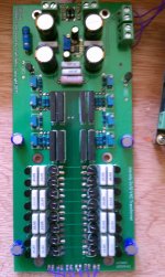
The first one is an LDR based source selector. The 16 black things are the LDRs and the 8 black things near the middle are solid state relays. To block or allow signal through you turn on or off the LDRs so it goes LDR>SSrelay?>LDR. SS goes to ground. They turn on or off opposite each other so you have 40R>near infinite R>40R for ON and for OFF you get 25Meg>2 to 4 R>25Meg.
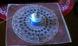
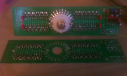
The other two pics are the proto and finished volume control. It uses a series LDR and then a shunt dale resistor. The dales change value by the rotary switch turning on/off solid state relays to select a resistor. The relay is between the resistor and ground. This way there are zero mechanical contacts on a stepped attenuator. Neat huh? The resistors arent shown in the last pic but they are vertically placed, 24 of them, from left to right across the board with 12 on each side.
A friend of mine is working on an Android app to replace the rotary switch. Even cooler!
Uriah
I have to disagree. I have two projects that use SS relays and I love them. The sound is wonderful and they are very reliable. I have an Audio Precision that says they have very low THD+N and no phase shift.
Enjoy the pics
The first one is an LDR based source selector. The 16 black things are the LDRs and the 8 black things near the middle are solid state relays. To block or allow signal through you turn on or off the LDRs so it goes LDR>SSrelay?>LDR. SS goes to ground. They turn on or off opposite each other so you have 40R>near infinite R>40R for ON and for OFF you get 25Meg>2 to 4 R>25Meg.
The other two pics are the proto and finished volume control. It uses a series LDR and then a shunt dale resistor. The dales change value by the rotary switch turning on/off solid state relays to select a resistor. The relay is between the resistor and ground. This way there are zero mechanical contacts on a stepped attenuator. Neat huh? The resistors arent shown in the last pic but they are vertically placed, 24 of them, from left to right across the board with 12 on each side.
A friend of mine is working on an Android app to replace the rotary switch. Even cooler!
Uriah
Attachments
Last edited:
If you want to do a project like this but the price of SS relays is a bit high for you then try ebay. You must use the kind that look like back to back mosfets or else you get DC problems on your signal, so if you find a great deal on ebay make sure its an optomos type of relay before buying. Panasonic had some really awesome ones but man they are soooo expensive. Like 9 dollars each. I stumbled upon a guy who was selling hundreds for around a dollar each so I bought them up and they sit on my shelf waiting for that special project that needs a SSR with a .5 ohm resistance. If you can handle 7 ohms or so then you can really start to afford a larger amount. Dont believe the datasheets on resistance either. Usually they test at half the datasheet values.
I also have designed one that uses SSR in the power supply so that the supply connects to the wall, fills super size caps, disconnects from the wall and waits til voltage drops to a preset minimum, then replays the process again. I need to get it on protoboard still and find out if it really reminds me of a battery as far as clean sound.
I also have designed one that uses SSR in the power supply so that the supply connects to the wall, fills super size caps, disconnects from the wall and waits til voltage drops to a preset minimum, then replays the process again. I need to get it on protoboard still and find out if it really reminds me of a battery as far as clean sound.
Rainwulf
I have to disagree. I have two projects that use SS relays and I love them. The sound is wonderful and they are very reliable. I have an Audio Precision that says they have very low THD+N and no phase shift.
Enjoy the pics
The first one is an LDR based source selector. The 16 black things are the LDRs and the 8 black things near the middle are solid state relays. To block or allow signal through you turn on or off the LDRs so it goes LDR>SSrelay?>LDR. SS goes to ground. They turn on or off opposite each other so you have 40R>near infinite R>40R for ON and for OFF you get 25Meg>2 to 4 R>25Meg.
The other two pics are the proto and finished volume control. It uses a series LDR and then a shunt dale resistor. The dales change value by the rotary switch turning on/off solid state relays to select a resistor. The relay is between the resistor and ground. This way there are zero mechanical contacts on a stepped attenuator. Neat huh? The resistors arent shown in the last pic but they are vertically placed, 24 of them, from left to right across the board with 12 on each side.
A friend of mine is working on an Android app to replace the rotary switch. Even cooler!
Uriah
wow! i dont even know what to say!!
But why is this better then a variable resistor?
Well in theory its either NOT as good or just as good. Here is the theory/reasoning for doing it:
If you read even 20 pages of the Lightspeed thread you will find a lot of argument and supposition with not much to back up the claims. You will also probably find GeorgeHiFi saying that mechanical contacts add noise to the signal and that the lack of mechanical contacts in a signal's circuit will result in better sound. He says this is one of the two reasons that LDRs sound so good as a potentiometer replacement. The other reason is the cadmium sulfide potentially sounds better than other resistive materials. I agreed with the cadmium sulfide argument but I also wondered about the mechanical contact argument. George got a hold of some super high power HP measurement equipment one day a few decades ago and did some measurements. While I cant recall the whole story he stated that inconsistencies in the contacts CONTACT allows microdiodes to form and causes noise when the AC signal jumps from side to side of these pockets of non-contact. A lot of people like to say electricity takes the path of least resistance but thats false. It takes every single path available to it to a greater or lesser degree determined by the amount of resistance in each path. So will a low level AC signal jump a micro gap in a contact? I believe it will and George had the opportunity to prove it to himself and relayed the story to us in the Lightspeed thread. Its in there somewhere. I do recall that the equipment was HP but anymore specifics that would help with a thread search are lost to me. You could ask him of course. So thats the reason stated for why LDRs sound so good. Lack of contacts and better material. I despise LDRs and love them at the same time. Matching them sucks and a lot of times they match in the jig and then you can never produce the same results again. They are highly effected by temp/voltage/schroedingers cat and anything else you can imagine so they are finicky devices. I would prefer to be able to use them in a shunt configuration where I can get the great sound of an LDR without having to adjust its value ever again. Just set it at 10k or so and forget it. Change the shunt resistors to adjust volume but have them be in a stepped attenuator so volume change is perfectly balanced from left to right channels. But the problem was how to keep a mechanical contact out of the signal and optomos is my solution to keeping a contact out of the signal. So your question of why is it better than a variable resistor: because a variable resistor is either an LDR and a pain in the rear to work with if it has to vary OR because a variable resistor would have a contact in the signal (wiper).
If you read even 20 pages of the Lightspeed thread you will find a lot of argument and supposition with not much to back up the claims. You will also probably find GeorgeHiFi saying that mechanical contacts add noise to the signal and that the lack of mechanical contacts in a signal's circuit will result in better sound. He says this is one of the two reasons that LDRs sound so good as a potentiometer replacement. The other reason is the cadmium sulfide potentially sounds better than other resistive materials. I agreed with the cadmium sulfide argument but I also wondered about the mechanical contact argument. George got a hold of some super high power HP measurement equipment one day a few decades ago and did some measurements. While I cant recall the whole story he stated that inconsistencies in the contacts CONTACT allows microdiodes to form and causes noise when the AC signal jumps from side to side of these pockets of non-contact. A lot of people like to say electricity takes the path of least resistance but thats false. It takes every single path available to it to a greater or lesser degree determined by the amount of resistance in each path. So will a low level AC signal jump a micro gap in a contact? I believe it will and George had the opportunity to prove it to himself and relayed the story to us in the Lightspeed thread. Its in there somewhere. I do recall that the equipment was HP but anymore specifics that would help with a thread search are lost to me. You could ask him of course. So thats the reason stated for why LDRs sound so good. Lack of contacts and better material. I despise LDRs and love them at the same time. Matching them sucks and a lot of times they match in the jig and then you can never produce the same results again. They are highly effected by temp/voltage/schroedingers cat and anything else you can imagine so they are finicky devices. I would prefer to be able to use them in a shunt configuration where I can get the great sound of an LDR without having to adjust its value ever again. Just set it at 10k or so and forget it. Change the shunt resistors to adjust volume but have them be in a stepped attenuator so volume change is perfectly balanced from left to right channels. But the problem was how to keep a mechanical contact out of the signal and optomos is my solution to keeping a contact out of the signal. So your question of why is it better than a variable resistor: because a variable resistor is either an LDR and a pain in the rear to work with if it has to vary OR because a variable resistor would have a contact in the signal (wiper).
I guess this should be brought back around to the topic. I definitely would attempt replacing a regular relay with a solid state relay if I was placing it from return to ground. However there are two things the would slow me down in the decision. Price. They arent cheap at all. Resistance. The less resistance the more expensive they are. A mechanical relay has zero ohms resistance while a SSR is going to have a few tenths of an ohm. In a 4 or 8 ohm speaker thats a significant amount of the total load.
Here is one that handles 15A(with small sink) and 60V with .1R.
http://www.ixysic.com/home/pdfs.nsf/www/CPC1909.pdf/$file/CPC1909.pdf
I was going to show how expensive it was but looks like Arrow only wants 5.70USD for it! Not bad at all.
Here is one that handles 15A(with small sink) and 60V with .1R.
http://www.ixysic.com/home/pdfs.nsf/www/CPC1909.pdf/$file/CPC1909.pdf
I was going to show how expensive it was but looks like Arrow only wants 5.70USD for it! Not bad at all.
Just looked at the CPC197* series and they can handle a LOT of current with a sink.
But why not try a DC SSR in the power supply rather than disconnecting the speaker? CPC1709 is a little less than $5 and can handle 22A with a small sink!! Put it (a pair/one on each rail) on the output side of the power supply so any error on the output of the amp means the amp instantly loses power? Could be done with a DC servo that uses an OPAMP and amplifies the DC then outputs it to the cathode side of a zener. The anode side of the zener would have a resistor to ground and the output from the zener would be taken from between the anode and resistor. Then that output would turn on/off the SSR!!
While this sounds cool it would result in the amp turning on/off very fast so there would have to be some sort of delay built in as well as turning it off until reset by human. There are some cheap and easy latching circuits that would solve this.
Man, this sounds like a product/project! We should start a build thread!
Last edited:
Link to the Diamond Cascode, a Diamond-like Buffer topology:
http://www.diyaudio.com/forums/anal...-like-buffer-current-booster.html#post3582199
The first few prototypes (called the LF07 v1.0) use an LM318M with a Class-A biased Diamond Cascode as a current booster, for use in a MyRef Rev C (any version with a DIP-8 socket for the LM318 - say v1.2..v1.4 PCBs).
I'm happy to say that it works, shows negligible output offsets for the first two prototypes (0.6 and 1.4 mV at the speaker out of the MyRef) and has excellent Class-A sonics, similar to or better than the LF01, but with even smaller form-factor and lower quiescent current. It's a drop-in upgrade for the LM318 with no other changes.
I'll also open an interest-check thread at the Group Buy forums after running a few tests and auditions with it.
I thought it would be a good idea to change a couple of resistors in my MyRef so i went ahead and changed them.
But in a stroke of stupidity, while reconnecting the amp, i connected the AC2 faston to PGND faston and vice versa, and powered the amp.
The leds glowed at first for a while and i heard a loud pop from the speakers.
Ok, so i must have fried something. I replaced the transistors (bc639, bc546) but still no go.
So I want your opinion and knowledge guys. Did i fry the lm3886, the lm318, the relay?
Thanks
Dario im using your LM317,LM337 ccs. Could these ic's been affected as well?
Verify voltage on zeners, if it's 12V on both they should be fine
... i connected the AC2 faston to PGND faston and vice versa, and powered the amp.
The leds glowed at first for a while and i heard a loud pop from the speakers.
Been there, done that. Check R11, the 1 ohm ground lift-resistor. If it's open, replace it and check - there's a 50:50 chance that all will be fine with just this fix.
If the R11 is fine, and the relay doesn't click, check all the rail voltages, then replace the LM318. Beyond that, further troubleshooting will be required to narrow down the failed components.
- Home
- Amplifiers
- Chip Amps
- My "audiophile" LM3886 approach