Peranders,
the open loop figure would be quoted with a load, say 8 ohms.
60 dB of feedback around that would be .oo8 ohms.
The Alephs are Drain output, as are many well regarded
designs, so I think we can assume that it really works.
Remember, the output device doesn't care (or even know)
which of the three possible modes it is in, common Base/
Collector/Emitter or if you like Grid/Plate/Cathode etc.
peranders said:
What do you mean?
Openloop gain of at 1000. How much feedback do you suggest?
Wanted gain must be 20-30 dB. 60 dB feedback gives 80-100 dB open-loop gain. Anybody will no fix that. Oscillations or a slow amp.
To some level i will agree with you. But even with 500 times feedback... That's 53dB + 20dB ... open loop gain of 5000 times. You would end up at 250mOhm.... That is if you test your openloopgain without a load.
Here we get back to Nelson's reply ... In a amp you would be likely to test the openloop gain into a predefined load .. For opamp's that could be 10k, 1k, 100R. For a audio power amp that would be 16R,8R,4R or 2R.
For the Musical Fidelity Amps. I think no one would disagree that they sounded bad for their time. And there is a lot of people who have build Nelson's amps... And i do think that a lot of people like them.
The most of them are collector or drain output design.. Real SE AMP'S are also mostly Collector or drain output.
Basicly i find it a good thing that some ... let's say nonEE persons come up with a amp design...
I think we should all help them correct errors not redesign the topology...
What i want to say is that i do not think we should kill others idears just because we do not like them our self.
Sonny
My amp etc
dshort9,
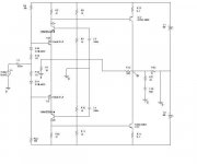
I looked at your diagram, noted the R15 I think, 10 Ohms Re in the input stage, and R1, R2, 5 Ohms on the input stage output side.
Your gain of this stage will be like the ratio of the 5 Ohm to 10 Ohms equals 0.5.....
Also, check your input impedance. I think it will be too low for comfort.
Cheers, Jan Didden
dshort9,
I looked at your diagram, noted the R15 I think, 10 Ohms Re in the input stage, and R1, R2, 5 Ohms on the input stage output side.
Your gain of this stage will be like the ratio of the 5 Ohm to 10 Ohms equals 0.5.....
Also, check your input impedance. I think it will be too low for comfort.
Cheers, Jan Didden
Output impedance
Feedback creates the output impedance if, and only if the open loop gain is big enough !!!!.
In this case I'm sorry to say that the open loop gain i too small.
The result is that the total gain is stronly dependent on the load.
I simulated the design with BJT's, and the BW is ok. But the harmonic distortion is awfull.
There is also a small problem with DC offset due to different BE voltages of NPN and PNP transistors.
You need a gain sektion to make it fly.
Simulation
Hello
Well, the BW was not bad, but there was alot of harmonic distortion.
Also there is an issue with DC offset. The working current of the output is about 1 [A], But can be changed by changing the walues af the 10 [ohm] resistors in the input stage.
Do you have spice ?
Good luck
Hello
Well, the BW was not bad, but there was alot of harmonic distortion.
Also there is an issue with DC offset. The working current of the output is about 1 [A], But can be changed by changing the walues af the 10 [ohm] resistors in the input stage.
Do you have spice ?
Good luck
My amp etc
Rens,
One remark if I may, the resistor R5 (47R) loads your signal current and limits the available open loop gain. You probably can't increase it because you'll increase the output stage standing current. However, if you replace R5 (and it's counterpart on the bottom side) with a current source of what is it, 13mA, your open loop gain goes way up, and THD goes way down. Since you only have two stages of gain, you probably won't have too much phaseshift around the loop so stability *shouldn't* be a problem. I still think you have a problem with bias stability though. What do you think?
Cheers, Jan Didden
Yes, you are correct, the open loop gain increases. What concerns me is having enough current to drive the outputs. They need about 50ma. for 5 amps out. This could be possible, as you say the input stage is not loaded by the 47R. I like it. Jens, I have not learned spice. Could you simulate this and see if it works? As far as bias stability, that is why I originally used small lateral mosfets instead of BC546, 556 as the input devices. If mounted with the output devices they have a negative tempco that would help stabilize the outputs, also a higher input impedance. 2SK216 and 2SJ79. See the first schematic in this thread.
- Status
- This old topic is closed. If you want to reopen this topic, contact a moderator using the "Report Post" button.
- Home
- Amplifiers
- Solid State
- My Amp Design