I want to build an active filter for my subs with a highpass for my mains. My mains are sealed boxes with an Fsc of 73hz and a Q=.7.
I am thinking a 2nd order highpass for the mains and a 4th order lowpass for the subs all at about 73hz. Does this sound ok? Then the crossover meets at -6dB at 73hz?
I am thinking a 2nd order highpass for the mains and a 4th order lowpass for the subs all at about 73hz. Does this sound ok? Then the crossover meets at -6dB at 73hz?
The plan itself sounds fine, but the best result depends on your room's acoustics. I would suggest crossing the mains over a bit higher than their Fs. Say, 90Hz or so. And I would match the F6 point of the sub xover to the F3 point of the main xover since you are using a 4th with a 2nd order.
IMO LR is be the best rolloff slope to shoot for with audio, so I would choose that slope to approximate with the filters. Have you simulated the design? TI makes a program called FilterPro that would be a good program to use, and of course there are circuit simulators that would work well also. Good luck!
IMO LR is be the best rolloff slope to shoot for with audio, so I would choose that slope to approximate with the filters. Have you simulated the design? TI makes a program called FilterPro that would be a good program to use, and of course there are circuit simulators that would work well also. Good luck!
I meant that with the rolloff from the box included with the electrical rolloff of the HP filter would bring the response down to -6dB @ the crossover point.
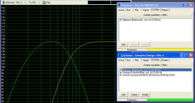
I was just simulating with WinISDpro Alpha using a 2nd order butterworth HP and a 4th order Linkwitz-Riley LP.
The natural rolloff of the mains (without a filter) seems to look more like a bessel filter with a more gradual rolloff than a 2nd order butterworth.
I was just simulating with WinISDpro Alpha using a 2nd order butterworth HP and a 4th order Linkwitz-Riley LP.
The natural rolloff of the mains (without a filter) seems to look more like a bessel filter with a more gradual rolloff than a 2nd order butterworth.
Attachments
merlinx76 said:I want to build an active filter for my subs with a highpass for my mains. My mains are sealed boxes with an Fsc of 73hz and a Q=.7.
I am thinking a 2nd order highpass for the mains and a 4th order lowpass for the subs all at about 73hz. Does this sound ok? Then the crossover meets at -6dB at 73hz?
That's exactly what I have been doing for years. It's a no brainer. My mids have a Q of .7 and an F3 of 90Hz so that's where I xover. Even at 90Hz the mid excursion is a tad much at high levels so for my next improvement I'll be looking at 120Hz or thereabouts.
I can't imagine what room acoustics has to do with it.
This is "theoretically" correct when You use an electronic 12dB HP-filter with Fsc=73Hz and Q=0.7 for the mains and a 24dB LR LP-filter with Fsc =73Hz for the sub.originally posted by merlinx76
I meant that with the rolloff from the box included with the electrical rolloff of the HP filter would bring the response down to -6dB @ the crossover point.
I say "theoretically" because as already mentioned, room acoustics (and baffle-step effects of Your "mains" as well) can have effects which might make it necessary to diverge from this "ideal" crossover to some extend, in order to achieve "ideal" (or improved) acoustic in- room response.
120Hz doesn`t matter for stereo-subs. For a mono sub 120 Hz would be too high IMO, even when crossed with a 4th-order LP.originally posted by Bill Fitzpatrick
Even at 90Hz the mid excursion is a tad much at high levels so for my next improvement I'll be looking at 120Hz or thereabouts.
Subwoofers have anything to do with room acoustics, always.originally posted by Bill Fitzpatrick
I can't imagine what room acoustics has to do with it.
cocolino said:
Subwoofers have anything to do with room acoustics, always.
I'm sure you going to offer an explation of what room acoustics have to do with the woofer to mid transition.
Are You kidding me Bill?I'm sure you going to offer an explation of what room acoustics have to do with the woofer to mid transition.
")
A linear woofer mid transition (I wouldn`t call crossing in the range from 70Hz to 120Hz exactly a woofer/mid* transition) depends on the room and where in the room the sub/satellites ("mains" or "mid" as You call it) are placed and how far away the drivers are mounted from each other and from the floor and other room boundaries.
For obvious reasons to a lesser extend, this apply also when sub and main speakers are not seperated but in one box.
The crossover has to account for this effects and if necessary to equalize them.
*for me, "mids" begin rather higher in frequency, say from about 300Hz upwards and in this frequency range room acoustics would have indeed less impact.
Taking in room FR measurements is a whole project in itself... and I can't afford much at the moment... Not sure what to do. The XO point could always be changed without much difficulty later on if necessary.
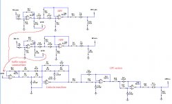
Here's what my circuit looks like (XO @ 72 hz)... It's already getting kinda big and complicated for me. I was trying to keep it as simple as I could.
I omitted the caps on the power leads of the opamps just to make it easier to follow.
Would there be a problem with crosstalk between the 2 channels the way I am mixing it?(do I need more buffers in there to prevent this?).
Any other problems?
note: I will not be using TL082's.
Here's what my circuit looks like (XO @ 72 hz)... It's already getting kinda big and complicated for me.
I was trying to keep it as simple as I could.I omitted the caps on the power leads of the opamps just to make it easier to follow.
Would there be a problem with crosstalk between the 2 channels the way I am mixing it?(do I need more buffers in there to prevent this?).
Any other problems?
note: I will not be using TL082's.
Attachments
cocolino said:
Are You kidding me Bill?
A linear woofer mid transition (I wouldn`t call crossing in the range from 70Hz to 120Hz exactly a woofer/mid* transition) depends on the room and where in the room the sub/satellites ("mains" or "mid" as You call it) are placed and how far away the drivers are mounted from each other and from the floor and other room boundaries.
For obvious reasons to a lesser extend, this apply also when sub and main speakers are not seperated but in one box.
The crossover has to account for this effects and if necessary to equalize them.
Now you got the woofers wandering around the room where they don't belong. Mine are no further from my listening post than the sats. So the room boundaries effect the sats no more or less than the subs at the crossover freq. I certainly wouldn't correct room problems in the crossover anymore than I would correct them with an equalizer. Maybe your woofer-mids aren't transitioning but mine are.
Bill,originally posted by Bill Fitzpatrick
Now you got the woofers wandering around the room where they don't belong. Mine are no further from my listening post than the sats. So the room boundaries effect the sats no more or less than the subs at the crossover freq. I certainly wouldn't correct room problems in the crossover anymore than I would correct them with an equalizer. Maybe your woofer-mids aren't transitioning but mine are.
I understand Your reasoning but there is at least one thing in the room which can be considered as a fixed element and which should be always adressed in the crossover - the floor.
I think You`ll agree that it makes a differenence for the sub/"mid" transition wether the sub-driver and/or the mid-driver is mounted near floor level or if it is on top of a 1,5m high box.
merlin,originally posted by merlinx76
Would there be a problem with crosstalk between the 2 channels the way I am mixing it?(do I need more buffers in there to prevent this?).
I haven`t recalculated if the values for Your aimed crossover frequencies are right but conceptionally I can see no flaws.
Only one (two things):
The input buffers output R`s (R1=100k, the other 100k I can`t read) which are going to Your sub`s summing amp. input are a bit high. I´d go with half of that - 50k or maybe even 25k.
A summing amp`s sums up via the input resistors on it`s "-" input. I can`t see it clearly if You got this right on Your drawing.
Sorry about the room acoustics thing. I wasn't trying to get anybody bent out of shape. It was more as a 'keep in mind' and maybe tweak later idea.
Merlin, your xover comes out just over 72Hz. Looks good.
I would also suggest lowering the summing resistors, R1 and R25, as cocolino suggests.
Merlin, your xover comes out just over 72Hz. Looks good.
I would also suggest lowering the summing resistors, R1 and R25, as cocolino suggests.
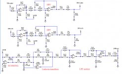
Summing amp fixed. See attachment
Should I take out the resistors I put in to compensate for the input bias current wherever I was able to (R20,R27,R28)? I see most circuits don't have them. Can they be detrimental in some way?
Also as far as component selection... What kind of caps should I use in the signal path and what opamps should I get without getting too exotic and expensive?
What about the caps on the power leads of the opamps (no shown on schematic)How do I determine how big they should be and what type of caps to use here? Would mylar caps be ok here since I already have a bunch?
Attachments
About the bias resistors - nobody puts them , true - but I do think ppl should pay attention to detail, so, good thinking. In your case though don't worry because:
- you don't need R20 and R27 , C1 and C10 will very quickly drop in their Z above DC - so you don't have any significant series input impedance to compensate for.
- you don't need R28 because you have an inverting configuration and you keep the noninverting input at ground level. The op amp will keep the inverting input at virtual ground.
More to the point, I'd rather scale down your resistor values for lower noise and lower potential HF pickup. You use up to 85 k. You could keep the values between 5k and 10k for best results (rescale caps of course, too).
And, do you need all those DC blockers anyway? The HP has a much higher cutoff than DC. If it does its job at all... no DC. Besides your power amp may even have another input DC filter.
The LP needs at most one DC filter, best at output. That is, IF your power amp doesn't have one at input anyway...
MBK
- but I do think ppl should pay attention to detail, so, good thinking. In your case though don't worry because:- you don't need R20 and R27 , C1 and C10 will very quickly drop in their Z above DC - so you don't have any significant series input impedance to compensate for.
- you don't need R28 because you have an inverting configuration and you keep the noninverting input at ground level. The op amp will keep the inverting input at virtual ground.
More to the point, I'd rather scale down your resistor values for lower noise and lower potential HF pickup. You use up to 85 k. You could keep the values between 5k and 10k for best results (rescale caps of course, too).
And, do you need all those DC blockers anyway? The HP has a much higher cutoff than DC. If it does its job at all... no DC. Besides your power amp may even have another input DC filter.
The LP needs at most one DC filter, best at output. That is, IF your power amp doesn't have one at input anyway...
MBK
originally posted by merlinx76
Also as far as component selection... What kind of caps should I use in the signal path and what opamps should I get without getting too exotic and expensive?
I`d go for MKP, KP (both Polypropylen) or KS (=Polystyrene respectively Styroflex as those things are called here in Europe) film caps. KS-film-caps might be a bit difficult to source (especially the bigger values, where 47nF is mostly already the biggest You can get) but MKP`s are readily avaiable and cheap.
About the opamps I barely dare to give a recommendation as there are so many different opinions.
Anyway, I´d say an OP604 (single version) or OP2604 (dual-version) isn`t neither exotic nor expensive or hard to get.
Certainly there may be better op-amps meanwhile but for something "unexotic" they really should work fine (at least they do for me).
how big is a 47nF styroflex?
A Styroflex film cap is bigger than an equivalent value/voltage MKP film cap.
The one`s I have are cubic parts 12,5x12,5x12,5mm (Siemens, 63V) but there are axial leaded versions also.
As I said 47nF is mostly the biggest value avaiable, also 100V seem to be the upper voltage limit in that they are to get.
Anything above 47nF or 100V I´d consider as quite "exotic".
mmthe 47nF is 12.5*12.5*12.5?
Yes, that`s right.
Most MKP`s of that value & voltage would only have about 1/4 of that volume.
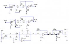
OK, I took out whatever I thought wasn't necessary. Less caps in the signal path. Can I take the outupts directly from the opamp like I have on the highpass section? Do I need a series resistor for the output or a resistor from output to ground?
I kept a cap on the output of the LPF for a bit of protection from subsonic freqs. (my sub amp has an input impedance of 5kohm)
I also reduced the value of most of the resistors throughout the circuit and changed all the caps accordingly.
Heres what I have now.
I kept a cap on the output of the LPF for a bit of protection from subsonic freqs. (my sub amp has an input impedance of 5kohm)
I also reduced the value of most of the resistors throughout the circuit and changed all the caps accordingly.
Heres what I have now.
Attachments
- Status
- This old topic is closed. If you want to reopen this topic, contact a moderator using the "Report Post" button.
- Home
- Amplifiers
- Chip Amps
- my active filter