I now have the exciting job of drilling and tapping 24 x m3 holes in the base plate for the 20mm tall motherboard standoffs to mount the amp modules.
To get these lined up perfectly straight on all axis is a real pain, so now I'm thinking of a plastic solution with one end having a flat sticky peel away section and the other end a pcb clip.
Does anybody know of a similar solution or product?
Dean
To get these lined up perfectly straight on all axis is a real pain, so now I'm thinking of a plastic solution with one end having a flat sticky peel away section and the other end a pcb clip.
Does anybody know of a similar solution or product?
Dean
Banned
Joined 2002
I now have the exciting job of drilling and tapping 24 x m3 holes in the base plate for the 20mm tall motherboard standoffs to mount the amp modules.
To get these lined up perfectly straight on all axis is a real pain, so now I'm thinking of a plastic solution with one end having a flat sticky peel away section and the other end a pcb clip.
Does anybody know of a similar solution or product?
Dean
what is it you are asking ?
Hi Dean, I just did the power measurements for both channels driven just before clipping into 8 ohm dummy loads.
P2P voltage was about 48V (which equates to 36W RMS). per channel. (50Hz sinewave)
at 20Hz it was 117.6W
at 50Hz power consumption was 120W
at 1Khz it was 123W
at 5Khz it was 120W
at 10Khz it was 119.8 W
at 20Khz it was 115.5W
pink noise at the same levels drew 50W.
and white noise at the same levels drew around 90W
So it is interesting that the peak value for yesterdays tests was 66W and that was definitely well above anything I would normally listen to.
edit this isn't apples for apples as yesterdays speaker load was 4 ohms. now playing the same tracks as yesterday with the dummy load and monitoring. seems to be running much lower, around 20W...
Tony.
Last edited:
Banned
Joined 2002
A plastic pcb standoffs about 20mm tall that can be stuck to the chassis and simply clip the lm4780 board on top.
Dean
ebay very cheap, do you want clip in through hole, OR do you want plastic stand offs that you can use screws with ?
Some are plastic with metal screws some are plastic and then use plastic screws.
OK just ran through the same tracks as yesterday with the same volume setting (50%) that was just before clipping with a sine wave. Unfortunately it is not possible to know whether the output levels on the CD are comparable.
Anyway the result was that it peaked at about 28W and generally was running down around 15-20W most of the time.
I cranked up to 80% on the volume control in windows, and it started running 20-25W most of the time, pushing into the low 30's with a peak of 51W This was most likely majorly overdriven compared to yesterday with real speakers.
I just tried the sine wave 1Khz into 4 ohms dummy load, single channel driven (as I only have two 8 ohm dummy loads), and got 48v p2p which is damn near 72W and double the 8 ohm power. Pretty impressive actually, and for theoretical max power the 300VA is probably about right.
So yesterdays peak of 66W playing pretty challenging music, was only using about 27% of the theoretical max power output of the amp.
Tony.
Nice one Tony.
With those numbers I cant see any problems with three of the 4780 chips running from the same 400VA supply.
Quite a bit of effort there mate, thanks for going the extra yard. I can use two tranny's and still install the third one later if I see the need.
I found these guys who seem to have a great range of the plastic standoffs I was looking for.
Crest Technologies - PCB Spacers / Supports / Standoffs
Cheers
Dean
Alternate Method for PCB Mounting
I have used modified PC motherboard mounts with great success. The results are much stronger than one would imagine. The adhesive on double sided foam tape settles and actually has to be scraped off after a few hours. Place all the standoffs on the PCB and then position on the floor of the case. This can keep a full size motherboard mounted vertically or flat.
I have used modified PC motherboard mounts with great success. The results are much stronger than one would imagine. The adhesive on double sided foam tape settles and actually has to be scraped off after a few hours. Place all the standoffs on the PCB and then position on the floor of the case. This can keep a full size motherboard mounted vertically or flat.
An externally hosted image should be here but it was not working when we last tested it.
An externally hosted image should be here but it was not working when we last tested it.
An externally hosted image should be here but it was not working when we last tested it.
An externally hosted image should be here but it was not working when we last tested it.
An externally hosted image should be here but it was not working when we last tested it.
Last edited:
Hi Dean, no problem I enjoyed doing the tests ")
for spacers I've used various. Jaycar have something like what Bob posted above, but have the adhesive on them already, not cheap and probably not tall enough though... 12.7mm Adhesive PCB Standoffs - Pk.25 - Jaycar Electronics
something like this may also work ok 20mm Screw Mount PCB Supports - Pk.25 - Jaycar Electronics self tapper in from the base, still have to drill holes though...
This is what I used last time. 19mm Nylon PCB Spacers - Pk.4 - Jaycar Electronics the clip in types are an absolute pain to remove the circuit board from if you need to pull it out later, screws on the circuit board to spacer are in my opinion worth it if you think you might want to take them out again again the problem with these is you will still need to drill the bottom of the case
Tony.
for spacers I've used various. Jaycar have something like what Bob posted above, but have the adhesive on them already, not cheap and probably not tall enough though... 12.7mm Adhesive PCB Standoffs - Pk.25 - Jaycar Electronics
something like this may also work ok 20mm Screw Mount PCB Supports - Pk.25 - Jaycar Electronics self tapper in from the base, still have to drill holes though...
This is what I used last time. 19mm Nylon PCB Spacers - Pk.4 - Jaycar Electronics the clip in types are an absolute pain to remove the circuit board from if you need to pull it out later, screws on the circuit board to spacer are in my opinion worth it if you think you might want to take them out again
again the problem with these is you will still need to drill the bottom of the case Tony.
I have gone with the stick on mount as it would be nearly impossible to drill and line up that many holes by hand.
I found a great supplier in Melbourne, Australia for heaps of little goodies and great prices.
Crest Technologies - Home
I ended up paying $10 for 50 x 6mm tall screw in sticky back pads. Perfect for the job and I can now screw normal standoffs into them, then screw the pcb onto that. Too easy.
I will be mounting the pcb's and starting the cabling today, and hopefully finish it by friday, before we go away overseas for 2 months
Thanks to the lads for the tests and pics. Solid feedback as always.
Dean
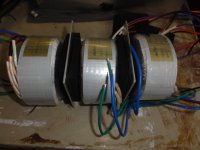
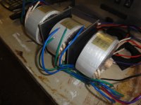
This is roughly how I plan to mount the toroidals.
As you can see I have a 12mm rubber/3mm Alloy/12mm Rubber sandwich setup.
There is a 25mm Dowel running through the center and so a 25mm hole through each layer.
Will this setup prevent EMI between toroidal's. What is the minimum distance/shielding in this case.
Dean
As you can see I have a 12mm rubber/3mm Alloy/12mm Rubber sandwich setup.
There is a 25mm Dowel running through the center and so a 25mm hole through each layer.
Will this setup prevent EMI between toroidal's. What is the minimum distance/shielding in this case.
Dean
Attachments
- Status
- This old topic is closed. If you want to reopen this topic, contact a moderator using the "Report Post" button.
- Home
- Amplifiers
- Chip Amps
- My 6 Channel LM4780 Wiring Diagram