BWRX said:To everyone who has a kit on the way - I just sent each of you emails containing documentation that will help with assembly.
Got it
")
dave
Banned
Joined 2002
planet10 said:Well, no problem finding room in the case
The amp boards are smaller than my regulator boards...
dave
When are you going to build your's Id like to hear them.
A couple of the folks in the US have received their kits and will eventually assemble them
Take your time and let me know if you have any questions.
Tonight I wired up 4 modules in a bridged stereo configuration - 2 modules (bridged) per speaker. And these are the speakers the amps were hooked up to - http://www.klipsch.com/products/details/rb-35.aspx That 125W max continuous rating is bull as I got the woofers to bottom out with a lot less than that! I didn't check the output to see if the signal was clipping, but it didn't sound like it was.
Bridged modules are a bit noisier because the output of the one module is connected to a ressitive divider that is fed to the other module's input so that the two modules are synched together and have the same input voltages, output voltages, and switching frequency. The resistor values and tolerances are critical and I used 1% metal films. The resistor values should have the same ratio as the values used on the amps themselves.
With the extra power available I had to crank up the volume and listen to some bass heavy music. The most startling track I played was "Blue Monday", track 7 from Orgy's Candyass CD. The quality and quantity of the bass was amazing. I felt like I was standing in front of the band at a concert and could hear the drummer hit the individual drums as he went down the line from right to left. My ears can still feel it a little bit I got yelled at to turn it down so my listening session didn't last that long anyway.
Take your time and let me know if you have any questions.
Tonight I wired up 4 modules in a bridged stereo configuration - 2 modules (bridged) per speaker. And these are the speakers the amps were hooked up to - http://www.klipsch.com/products/details/rb-35.aspx That 125W max continuous rating is bull as I got the woofers to bottom out with a lot less than that! I didn't check the output to see if the signal was clipping, but it didn't sound like it was.
Bridged modules are a bit noisier because the output of the one module is connected to a ressitive divider that is fed to the other module's input so that the two modules are synched together and have the same input voltages, output voltages, and switching frequency. The resistor values and tolerances are critical and I used 1% metal films. The resistor values should have the same ratio as the values used on the amps themselves.
With the extra power available I had to crank up the volume and listen to some bass heavy music. The most startling track I played was "Blue Monday", track 7 from Orgy's Candyass CD. The quality and quantity of the bass was amazing. I felt like I was standing in front of the band at a concert and could hear the drummer hit the individual drums as he went down the line from right to left. My ears can still feel it a little bit
I got yelled at to turn it down so my listening session didn't last that long anyway.I've got some modules, an analog scope, one good scope probe, a digital camera, 8 ohm power resistors, and my ipod loaded with test tones (10Hz, 20Hz, 100Hz, 200Hz, 1kHz, 2kHz, 10kHz, 20kHz) all ready for some testing tomorrow (finally have some time!). I'll take photos of the scope with the camera and post them here to show the various waveforms of the modules (single ended and bridged) under normal and maximum output conditions.
If anyone has a request for a test I can do with that setup just let me know. I briefly ran through the 10Hz-20kHz waveforms tonight with an 8 ohm load on the bridged modules and the output voltage didn't vary at all. In other words - ruler flat frequency response.
The switching residual looks quite clean as well with only minimal overshoot and hardly any ringing at all. This could partly be due to my 15MHz scope, but I have the probe grounded right at the output ground and set to 10x for the best accuracy. Look for more information tomorrow.
I can't measure directly across the bridged outputs but I can measure each output separately with respect to ground. Both outputs are at ground potential with no input signal (unlike Tripath based amps where the outputs sit at half the supply voltage) because of the split rail supply. I wish I had a second working probe so I could see the timing between the two waveforms...
Oh well, time to get some scope shots
Oh well, time to get some scope shots
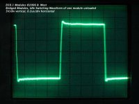
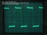
Attached is a photo of the switching waveform of one module of a bridged pair while idling. From the scaling you can see that the idle switching frequency is around 625kHz for the modules I tested. These had different value feedback caps and resistors that set the gain to 3.9V/V and lowered the switching frequency a little compared to the values that were sent out with the kits. The value of the feedback components in the kits set the gain to 8.2V/V and the idle switching frequency to around 660kHz.
This photo shows that the snubber could be further optimized to reduce the initial overshoot and further dampen the slight ringing. A slightly higher value resistor would be something I'd eventually like to try. As it is, the overshoot does not seem to be audible at all.
This photo shows that the snubber could be further optimized to reduce the initial overshoot and further dampen the slight ringing. A slightly higher value resistor would be something I'd eventually like to try. As it is, the overshoot does not seem to be audible at all.
Attachments
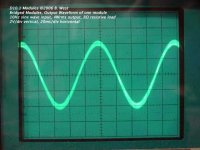
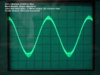
This is the output of one module of a bridged pair with a 20kHz sine wave input.
The input level was not changed and the output level did not change either, at a constant 4Wrms output power into an 8 ohm resistive load over the 10Hz-20kHz frequency range.
The output power is 4Wrms because I forgot I was measuring bridged modules and set the level so the output of one module had an amplitude of 4V which is 1Wrms @ 8 ohm for a single ended amp and 4Wrms @ 8 ohm for a bridged amp.
Attachments
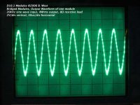
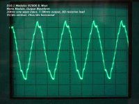
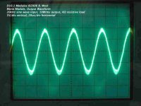
Mono module, 20kHz sine wave, 10Wrms output @ 4 ohms.
The frequency response was flat across the band at 8 ohms but drooped a little bit below 100Hz and around 20kHz with a 4 ohm load. Clearly the modules are more optimized for 8 ohm loads, but the tiny bit of droop at the extremes with a 4 ohm load would be very hard to notice, especially at the high end.
The frequency response was flat across the band at 8 ohms but drooped a little bit below 100Hz and around 20kHz with a 4 ohm load. Clearly the modules are more optimized for 8 ohm loads, but the tiny bit of droop at the extremes with a 4 ohm load would be very hard to notice, especially at the high end.
Attachments
A comparison?
A comparison between you working prototype and a "regular" amp of equal power might be in order .... No?
It seems to my that the 'scope traces may be "gained up" a little to get a good camera shot (?).
Otherwise ... this is very valuable information. Keep up the good work.

A comparison between you working prototype and a "regular" amp of equal power might be in order .... No?
It seems to my that the 'scope traces may be "gained up" a little to get a good camera shot (?).
Otherwise ... this is very valuable information. Keep up the good work.
These could go into production the way they are now, so they're out of the prototype phase. That doesn't mean they wouldn't benefit from tweaking certain component values.
A comparison to a regular class ab amp isn't of much value to me, but I'm sure those that got the kits will eventually be able to provide some comparisons to amps they've been listening to.
What does "gained up" mean? My scope is an old 15MHz Tektronix T922 so it certainly isn't top of the line, but I tried to do the best I could with my camera to capture the waveforms. It's really hard to get the trigger set just right so the waveform is still on the screen, and even then the scope runs out of intensity when the horizontal scaling is so low. I had to set my camera shutter to stay open longer to get the low frequency waveforms otherwise the shutter was way faster than the scope tracing the waveform! If you send me a nicer scope and a couple good probes I'll gladly do the tests again
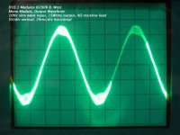
In the 20kHz 4ohm waveform I got the trigger just right and you can see the residual switching ripple quite nicely in the output waveform. Even with it switching at 625kHz it looks pretty rough, which shows how higher switching frequencies would be more beneficial for accurate reproduction. I'll try to "overclock" one of the old modules and see how it handles (and sounds) switching around 1MHz.
I also forgot to mention that I got the little chips really hot during full power testing! I almost burned my finger touching the chip doing the low frequency tests into 4ohms... My supply regulators got very hot too, as well as the resistive load, so there was some serious current flowing through the mosfets on that little SOIC chip. It's pretty amazing it can handle that kind of current if you ask me.
A comparison to a regular class ab amp isn't of much value to me, but I'm sure those that got the kits will eventually be able to provide some comparisons to amps they've been listening to.
What does "gained up" mean? My scope is an old 15MHz Tektronix T922 so it certainly isn't top of the line, but I tried to do the best I could with my camera to capture the waveforms. It's really hard to get the trigger set just right so the waveform is still on the screen, and even then the scope runs out of intensity when the horizontal scaling is so low. I had to set my camera shutter to stay open longer to get the low frequency waveforms otherwise the shutter was way faster than the scope tracing the waveform! If you send me a nicer scope and a couple good probes I'll gladly do the tests again
In the 20kHz 4ohm waveform I got the trigger just right and you can see the residual switching ripple quite nicely in the output waveform. Even with it switching at 625kHz it looks pretty rough, which shows how higher switching frequencies would be more beneficial for accurate reproduction. I'll try to "overclock"
one of the old modules and see how it handles (and sounds) switching around 1MHz.I also forgot to mention that I got the little chips really hot during full power testing! I almost burned my finger touching the chip doing the low frequency tests into 4ohms... My supply regulators got very hot too, as well as the resistive load, so there was some serious current flowing through the mosfets on that little SOIC chip. It's pretty amazing it can handle that kind of current if you ask me.
- Status
- This old topic is closed. If you want to reopen this topic, contact a moderator using the "Report Post" button.
- Home
- Amplifiers
- Class D
- My 10W Mono Single-Ended modules - D10.1