Transistor identufication on RCD-975
The above thread link is for the RCD855 model with different schematics. Are you able to point them out in this attached picture?
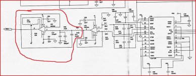
There three 3/4 moon transistors in sockets T301 (next to two capacitor) plus T302 and T303 (next to each other) along outside edge of PCB (on right side of CD player). Are these the muting transistors?
If I understand correctly they are just un-soldered with flux? No further bridge wire soldering of the empty circuit board holes is required?
Thanks in advance, Roger
The above thread link is for the RCD855 model with different schematics. Are you able to point them out in this attached picture?
There three 3/4 moon transistors in sockets T301 (next to two capacitor) plus T302 and T303 (next to each other) along outside edge of PCB (on right side of CD player). Are these the muting transistors?
If I understand correctly they are just un-soldered with flux? No further bridge wire soldering of the empty circuit board holes is required?
Thanks in advance, Roger
Attachments
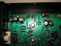
Is that a relay near the sockets (RY301) ?
Looks like it uses a relay for muting rather than transistors")
Edit... maybe there are different versions of this player. The two unused transistor locations T306 and 307 near the relay look as though they could be mute transistors (if fitted) and used instead of a relay. The transistors you circled appear to be in the wrong physical location to be anything to do with muting, more likely regulators in view of the diode and caps nearby.
As ever examination of the circuit is essential before attempting any mods... a little knowledge can be a dangerous thing
Looks like it uses a relay for muting rather than transistors
Edit... maybe there are different versions of this player. The two unused transistor locations T306 and 307 near the relay look as though they could be mute transistors (if fitted) and used instead of a relay. The transistors you circled appear to be in the wrong physical location to be anything to do with muting, more likely regulators in view of the diode and caps nearby.
As ever examination of the circuit is essential before attempting any mods... a little knowledge can be a dangerous thing
Last edited:
Parts and PCB
Hi Moly,
thanks for your prompt reply.
The parts list says: RY301 LY00000459 RELAY RSA-12. See PCB connection schematics enclosed. Is that the muting component? Can it be unsoldered without other changes?
Also, the 3/4 moon transistors that appear to be closely connected to the relay are:
T302,T303 TR70000194 TRANSISTOR BC547B
T301 TR70000200 TRANSISTOR BC557B
While I'm at it, can you advice on another forum's post suggesting "test removing small value film or ceramic capacitor from output to ground. The purpose if that capacitor is to reduce risk of interference from other devices and mobile phones. This forms a lowpass for output signal". Which will affect bass. "Try removing one channel capacity and go lower capacitance if bass holds up fine".
Assume these would be the C356 and C357 parts: CAP Polystyrene 160V 1000PF?
Regards, Roger
Attachments
Additiona schematic diagram for RCD-975
The following may also assist.
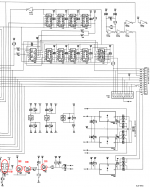
All the service manual downloads seem to be of the same poor photocopy/scan version. However think I managed to find and indicate C356, C357 on attached diagram (1) and T301, T302, T303 plus RY301 on attached diagram (2).
(A comment on the schematic state that T306 and T307 are not used in the RCD-975.)
The following may also assist.
All the service manual downloads seem to be of the same poor photocopy/scan version. However think I managed to find and indicate C356, C357 on attached diagram (1) and T301, T302, T303 plus RY301 on attached diagram (2).
(A comment on the schematic state that T306 and T307 are not used in the RCD-975.)
Attachments
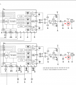
A bit hard to make out clearly but the relay appears to work by shorting the signal to ground to mute the audio rather than simply being in series with the audio.
I would have expected nothing less tbh. So what that means, is that the relay has to all intents and purposes zero effect on the audio... as audio doesn't pass through it at all in play mode.
The cap you have marked is strange. Fitting a cap to prevent stray RF is normally done at the input to an audio stage i.e. in the amp or preamp.
I wouldn't be 100% sure that it's purpose is to prevent interference as used here. The output of the DAC is coupled directly to the differential amp (the opamp) with no other hf filtering at all which is very very unusual. The filter is to reduce the amplitude of hf from the DAC. Is it a TDA1305... which is a bitstream DAC? All D/A convertors produce this hf. The early players without oversampling used a brickwall filter with a steep cut off response, oversampling and bitstream produced hf artifacts that were much higher in frequency and consequently much easier to filter out "gently" often with a simple filter... such as this.
I think you will find the cap is best left exactly as is, removing it will probably cause a large increase in ultrasonic signal along with the audio. If you have a scope it would be interesting to see what hf is present.
Edit... that cap doesn't alter the bass in any way. Increasing it's value would roll of the treble earlier and omiting it as mentioned will extend the treble (or rather hf response) allowing ultasonic hash through.
Last edited:
TDA1305T data sheet link
"The TDA1305T features a unique combination of bitstream and continuous calibration techniques."
TDA1305T datasheet, Pinout ,application circuits TDA1305T Stereo 1fs Data Input Up-sampling Filter With Bitstream Continuous Dual DAC (BCC-DAC2)
"The TDA1305T features a unique combination of bitstream and continuous calibration techniques."
TDA1305T datasheet, Pinout ,application circuits TDA1305T Stereo 1fs Data Input Up-sampling Filter With Bitstream Continuous Dual DAC (BCC-DAC2)
It's a good DAC... capable of excellent performance.
I'm sure that cap is an essential part of the filter arrangement, it's just done in a slightly different way to what you normally see. It also may explain why the opamp has the extra transistors added as normally they would not be required for an opamp based line out stage. The cap and resistor filter add a significant load at hf, hence the transistors.
Here's another implementation of the TDA1305 this time with a more conventional filter wrapped around an opamp stage.
So I would definitely leave the cap in place.
Attachments
Other mods questions thread
Started a new thread with question about other specific mod recommendations.
http://www.diyaudio.com/forums/digital-source/180646-modification-suggestions-rotel-rcd-975-a.html
Started a new thread with question about other specific mod recommendations.
http://www.diyaudio.com/forums/digital-source/180646-modification-suggestions-rotel-rcd-975-a.html
Cap replacements for similar effect
Since the analog output stage seems a target for mods - would replacing the caps in the output stage for better quality ones provide a similar improvement?
If so, which ones to replace in the first instance and what do I replace them with?
Assume same V/uF values should be kept?
Since the analog output stage seems a target for mods - would replacing the caps in the output stage for better quality ones provide a similar improvement?
If so, which ones to replace in the first instance and what do I replace them with?
Assume same V/uF values should be kept?
Only the 100uf cap could be changed really, and tbh, any perceived gains would more than likely just be wishful thinking. I wouldn't short it out as the relay pulls the output to ground and that could upset the feedback under start up conditions.
Changing the opamp is a definite area to look at, and I'm going to go with one of my favourites and say OPA604. Solder direct to the PCB, don't use a socket and also add a small cap of 0.047 to 0.1uf direct across the supply pins soldering to the IC itself.
If you haven't a scope that's as far as I would go... if you have I would look at the output of the opamp direct and see what level of HF is present and perhaps even try removing the output stage transistors as the OPA604 has a pretty decent current delivery. You could try that without a scope of course... but it's good to see what is actually happening.
Personally I don't use or like sockets... they add a little stray capacitance and also raise the impedance of the supply as seen by the opamp... but they can be useful for quick evaluating of devices.
A small cap direct on the supply pins gives a low impedance at HF which is essential for stability with many very wide bandwidth opamps. Some will argue that the cap should really e in series with a small (1 ohm or so) resistor. On linear supplies where the rails are essentially clean anyway I have never found an issue and the cap on its own is fine.
Can't really comment on the discrete ones other than to say that a "large" unshielded PCB will be prone to stray pickup and that although certain aspects of the design may seem appealing I can't believe it can compete with modern purpose designed devices that have had huge resources thrown at them.
This was from an earlier thread...
http://www.diyaudio.com/forums/chip...g-audio-integrated-opamps-55.html#post2018832
Like your suggestion of OPA604APG4 + caps. Any caps you can suggest in particular? How would you characterise the sound in your setup?
Looked at the earlier thread you referred to and others. Everybody has their opinion. With popular choices:
LT1028ACN8 (neutral with good bass)
LME49860 (good compatibility) couldn't find exact model number?
AD797BRZ (x4 +2:1 adapter)
AD8620ARZ (with a similar CAP addition as yours - I think)
The Audio-gd discrete opamp circuits seem to be best with +-15V (does my supply do this?). Earth model the safer choice with "3-D sound". Then there is the IC vs discrete argument...
Depends on the TDA1305T and other circuit matching as well.
My Cyrus 8vs2 and Focal DIY speakers are very "detailed" but on the lean side (could do with 2ohm resistors on tweeters to balance sensitivity for starters). Maybe the LT1028 may be a good match with its realistic bass? Although next upgrade is probably a pre-amp, active filter and power amps.
Any caps like this are fine. The leads can be spaced easily to fit exactly across the supply pins direct on the opamp.
--|MCRR25104X7RK0050|CAPACITOR, 100NF 50V | CPC
Your circuit piccy doesn't show the supply clearly enough so I would just measure and be sure from ground to pin 4 and pin 7.
All I can say as for what to use is try a few as it's so personal a choice. The OPA604 is (to me) very musical with no edginess or stridency at all. I used an OPA604 and AD845 in my micromega... which is what the snip in post 9 is
There's nothing like a bit of marketing waffle, have a scroll down to "sound quality" near the end,
http://www.datasheetcatalog.org/datasheet/BurrBrown/mXyzsxss.pdf
- Status
- This old topic is closed. If you want to reopen this topic, contact a moderator using the "Report Post" button.
- Home
- Source & Line
- Digital Source
- muting transistors / Rotel RCD-975