Hi Eli,
I may be interested in some of these Siberian '70s Svetlanas. Do you have any experience or reports of their sound quality?
andy
I can't comment.
I used these 6B4Gs recently. They were a reasonably well matched quad at about half the price of Sovteks, and not much more than Russian NOS. Good value, I reckon.
Hey All,
I have a question about the EL34 musical machine. On the input there is a 100k pot and beyond it the voltage .785. does this mean the voltage should max out at .785 or be set at .785?
I'm using HK output transformers and a Fisher power transformer. I happened on to a matched quad of Siemans EL34's and some, what were sold to me as Mullard 6GK5's. The 6gk5's came in purple Pro/Comm boxes and are labeled made in Great Britain. Are they actually Mullards?
I'm guessing at bit here, but the .785V ac may be an indication of the input sensitivity of the MM.
One other thing (after looking at the schemo) Poinz' is not showing any grid stopper R's on the 6GK5's, but SY and a few other folks here recommended adding them. Use carbon comp R's.
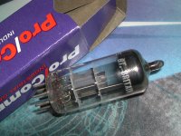
The 6GK5's in the ProComm boxes sound like the ones that Stan sells at ESRC in Orlando. I have about 20 of these, see pic. The ones I have have 2 seams on the top of the glass and say "gt. britain" next to the 6GK5 ink. These are Mullards.
One other thing (after looking at the schemo) Poinz' is not showing any grid stopper R's on the 6GK5's, but SY and a few other folks here recommended adding them. Use carbon comp R's.
The 6GK5's in the ProComm boxes sound like the ones that Stan sells at ESRC in Orlando. I have about 20 of these, see pic. The ones I have have 2 seams on the top of the glass and say "gt. britain" next to the 6GK5 ink. These are Mullards.
Attachments
Last edited:
Thanks boywonder,
It seems logical that the .785 is a maximum input. Yes they are the same Mullards that you have. Woo Hoo! I also have 8 NOS Hitachi 6GK5's to try as well.
I think this design could be modified to use 6550's couldn't it?
I've heard others mention that carbon composition make good grid stoppers, (and nothing else). Does 1k sound right?
What about carbon film?
Kevin
I think this design could be modified to use 6550's couldn't it?
Kevin
I don't think that the 6GK5 has the voltage swing to fully drive 6550's/KT88's. The miller C is higher with those tubes as well, requiring a fair bit of gm. IIRC, I popped some KT88's in my MM when I had it on the bench, and got similar power out as the EL34's. That was a few years ago.
One other minor mod you may want to consider is the bias circuit. The way it's shown in the schemo, if the pot wiper lifts the bias goes away, leading to red plates. One project that comes to mind for a safer bias arrangement is the mullard KT88 project thread started by Tubemack; there are lots of other projects with similar bias arrangements around as well.
Attachments
Last edited:
BoyWonder.
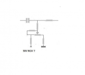
I see what you mean. If you use the 27k / 22k voltage divider and then use the pot to adjust the voltage within the divider if the wiper fails you still have minimum bias not zero bias. I've attached a schematic to show my change. I hope/ think its correct?
I see what you mean. If you use the 27k / 22k voltage divider and then use the pot to adjust the voltage within the divider if the wiper fails you still have minimum bias not zero bias. I've attached a schematic to show my change. I hope/ think its correct?
Attachments
Correction
Thanks Tinitus,
I think it amounts to the same thing. Two voltage dividers in parallel. One variable and the other set. I think I have it right nowThe lower set divider, 37/22k divider yields 24.6 volts. The adjustable divider, 27/10/22k yields between 24.6 and 35.8 volts. Which makes gives the same range of adjustment as the original design. But if the wiper fails the minimum bias voltage becomes 24.6, the set divider output.
Attachments
Last edited:
Hey All,
I was looking at Poindexters schematic just now and he labels the plate as 6. From my information the plate is 5. And 6 is not connected? Is this a typo?
Assuming that you are talking about the 6GK5, you are correct; the plate is pin 5. On the Poinz schemo I have, he has the upper 6GK5 plate labeled as 5 and the lower 6GK5 labeled as 6........a typo.
CCS
Hey All,
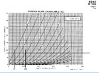
I'm trying to understand how a constant current source functions using load lines. I'm assuming that if current is set, in this case at 8ma per tube. And maximum input is .785 volts in either direction, centered at .5 volts. The voltage swing would be about 78 volts with maximum output of .92 watts and 115 volts @8ma.
Math is not my strong point. But do these calculations seem accurate? I've included a graph that I hope shows what I'm thinking.
Hey All,
I'm trying to understand how a constant current source functions using load lines. I'm assuming that if current is set, in this case at 8ma per tube. And maximum input is .785 volts in either direction, centered at .5 volts. The voltage swing would be about 78 volts with maximum output of .92 watts and 115 volts @8ma.
Math is not my strong point. But do these calculations seem accurate? I've included a graph that I hope shows what I'm thinking.
Attachments
Do you mean .785V/2? If you mean .785 + and - then you will go beyond the 0V grid. Maybe -1V is a better bias point?
Hey All,
I'm trying to understand how a constant current source functions using load lines. I'm assuming that if current is set, in this case at 8ma per tube. And maximum input is .785 volts in either direction, centered at .5 volts. The voltage swing would be about 78 volts with maximum output of .92 watts and 115 volts @8ma.
Math is not my strong point. But do these calculations seem accurate? I've included a graph that I hope shows what I'm thinking.
Last edited:
So you can still set the bias point? I guess you would still be able to by doing the calculation for the cathode resistor. The ma doesn't change much but the voltage does. So if the input voltage maxes out at .785 the input range is between 0 and .785? Not +.785 and -.785?
So you can still set the bias point? I guess you would still be able to by doing the calculation for the cathode resistor. The ma doesn't change much but the voltage does. So if the input voltage maxes out at .785 the input range is between 0 and .785? Not +.785 and -.785?
I found the 6GK5/EL34 schematic using the 10M45S for the LTP CCS. I should have read through the thread and actually knew what I was commenting on, before I commented about the bias.
It appears that the input voltage would be 0.785V P-P.
Last edited:
Kevin: Your revised bias schemo in post # 32 doesn't help when the pot wiper goes open, it just burns more current from the bias circuit from the additional resistors in parallel.
Take another look at the schematic I posted in post #29; the extra R divider chain connects to the grids.
Take another look at the schematic I posted in post #29; the extra R divider chain connects to the grids.
- Status
- This old topic is closed. If you want to reopen this topic, contact a moderator using the "Report Post" button.
- Home
- Amplifiers
- Tubes / Valves
- Musical Machine (triode PP EL34) question(s)