It is easier to do it the other way around, you can connect a small filament transformer (5V or 6.3V) to the secondary and measure the AC voltage on the primary. I would expect the turns ratio to be 20~25. Since there are no extra taps on the OPT, the UL option does not exist.
I've measured both OT's. Inductance for the left one: anode-anode=3,9H (resistance 101,5ohm), anode-B+=1H. Right one anode-anode=5,8H (resistance 98ohm), anode-B+=1,5H. I've also connected 9,2VAC to 8ohm secondary tap. Results are: left 208Vac, right 211Vac.
The inductance difference between channels is almost 50%. I've rechecked three times. How could it be? Resistance is almost the same.
The inductance difference between channels is almost 50%. I've rechecked three times. How could it be? Resistance is almost the same.
The turns ratio is about 22.5~23, so call it Zr ~ 4k:8, just like what the datasheets recommended. The inductance is effected by the drive level and the frequency used for the measurement, I am not sure what your meter is rated for, but very few of them are capable of making accurate measurements on tube amp OPT's.
Now that we have most of the parameters about the amplifier, what is that you would like to do? Figure out the feedback loop? Modify the design? What else?
Now that we have most of the parameters about the amplifier, what is that you would like to do? Figure out the feedback loop? Modify the design? What else?
My goal is to achieve maximum from XD800. To achieve this, the B+ should be rised to get more power, driver tubes should be strong enough to drive kt88 without problems, and feedback loops should be tweaked to these mods. Could you tell me what is the maximum voltage for kt88 push pull triode operation with fixed bias?
It seems like you want to change the PT to get the maximum output from a pair of triode-connected KT88's, is this correct? If so, we can forget the limits for the pentode connection, also as ruben mentioned, if you up the voltage, then many of the capacitors need to be replaced as well, is that what you want to do?Could you tell me what is the maximum voltage for kt88 push pull triode operation with fixed bias?
Guys, as I mentioned earlier I've already changed power tubes power supply caps to 500V. When about 475Vdc B+, voltage doubler caps will be at it's limit. I changed them from 470u/220V to 470u/250V ones. And 250V on them will be when B+ will rise to 475Vdc. I've simulated it in PSU Designer II. So firstly I'll have to change these caps for higher voltage rating.
After this month of listening to this amp I figured out that mainly I've listened to triode mode, so I think I should go as far with B+ as this mode allows.
KT88 Svetlana
ABSOLUTE MAXIMUM RATINGS
Cathode-heater maximum DC voltage +-250v
Allowable spot temperature on envel. 250 degrees C
Plate voltage, DC (at idle) 820 v
Plate voltage, DC, in triode connection 610 v
Screen voltage, DC, at idle 610 v
Control grid voltage, DC, at idle -350 v
Cathode current, DC, at idle 235 mA
Plate dissipation, peak or idle 44 watts
Screen grid dissipation, peak or idle 10 watts
Control grid resistance, fixed bias 220k ohms
Push-pull class AB1 triode connection, fixed bias
Plate and screen voltage 480v DC
Plate plus screen current, idle 120 mA
Plate plus screen current, full power 150 mA
Grid bias -65 v DC
Load resistance, plate-to-plate 4000 ohms
Output power 30 watts
Total harmonic distortion at 30w out 1.5%
Push-pull class AB1 tetrode connection, fixed bias
Plate voltage 560v DC
Screen voltage 300v DC
Plate current, idle 120 mA
Plate current, full power 290 mA
Grid bias -45 v DC
Load resistance, plate-to-plate 4500 ohms
Output power 100 watts
Total harmonic distortion at 100w out 2.5%
I'll take off power trafos enclosures and paste some pictures. After this I'll decide what to do. I hear ligh buzz from them so I'll check them also.
If you prefer to listen to the triode-connection and your speakers are relatively efficient, hopefully >90dB/W/m, then a good option is to operate the output stage in pure class A, in which case, you do not need the large filter capacitance to reduce the ripple, so you can use capacitors with higher voltage ratings, e.g., 220uF/450V stacked. What do you think?
My speakers are about 86dB so not much. I listen very different kinds of music, from jazz and vocals, electronic to hard rock and drum and bass, which I like as loud as it can be. Because of this I also don't want to remove triode/tetrode switch and that is why I want to increase B+ rail.
How much power would amp achieve with pure class A driver? In present circuit the amp works in class A to first few watts only.
Do you have any experience with CCS anode load? I ask because it should decrease THD and I would omit large and hot anode resistors for 6N6P.
How much power would amp achieve with pure class A driver? In present circuit the amp works in class A to first few watts only.
Do you have any experience with CCS anode load? I ask because it should decrease THD and I would omit large and hot anode resistors for 6N6P.
I see, so you need both pentode and triode modes. There is another thing to consider, if you replace the power transformer to get higher B+ voltage, I am not sure if the output transformers can handle the extra power in pentode mode. With a pair of KT88's, you can easily get 100W but that might be too much for the OPT's. In any case, we'll find out after you test the power transformer.
Zapodaj.Net - Darmowy hosting zdj?? i obrazków bez rejestracji! - 211715d38cf69.jpg
Zapodaj.Net - Darmowy hosting zdj?? i obrazków bez rejestracji! - 9cf11f063c84f.jpg
I've removed power transformer enclosures. The trafo size are EI105/56. Both looks good and enough powerful. Honestly I thought they will be small and underpowered, but I'm surprised. There is a small space to put some more wire and increase the B+ rail. I will take off paper outside cover and see how much wire can be added. If OT's are equally made I think these few volts more will not hurt them. Now they are slightly warm after long listen. I think I will also mount trafos on rubber distances to remove the light buzz from trafos vibrations.
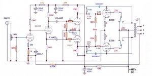
In the schematic shown above, there does not appear to be a way to change the bias voltage when swiching between the pentode and triode modes. If you want to maximize the performance for both modes, you will need address that issue. Also, for the triode mode, the drivers have to swing quie a bit more voltage, not sure if the ECC82's are up to the task...
I will set bias to triode mode, tetrode mode will have to live with that") For now I don't have enough experience to predict how it will influence to the sound in tetrode mode.
For now I don't have enough experience to predict how it will influence to the sound in tetrode mode.
That is why I've changed ECC82 to 6N6P which have 8W power dissipation. Do you think 200V 20mA operating point will be enough to drive KT88 in both modes?
For now I don't have enough experience to predict how it will influence to the sound in tetrode mode.That is why I've changed ECC82 to 6N6P which have 8W power dissipation. Do you think 200V 20mA operating point will be enough to drive KT88 in both modes?
Just another thought on the bias, if you optimize for triode operation, then the pentode mode will operate in near class B - not so good for hi-fi... But with some work, it is possible to optimize the different bias requirements but it will require a few more components and a switch.
After many thoughts I ended up with factory version. As You said, original transformers are too weak, and changing them too expensive. I tried few versions of driver/input tube changes and always had a problem with not enough microdetails in sound. I made an amp from what I could find in my basement for time without music angel. It is SE GU50/6e5p choke loaded with unbypassed cathodes in both driver/output tubes. Running at 100mA and B+ about 450VDC and it is so much better than MA even with my Dynaudio Geminis, that I couldn't believe. So I made my MA to factory version and sold it. I think that upgrading this amp is too expensive, because You should change transformers and circuit with driver/input tubes. The best way, in my opinion ofcourse, is to make something diy from the beginning. There are so many good sounding tubes around we could use making own amps
Thanks Everyone for help.
Best Regards,
Daniel
Thanks Everyone for help.
Best Regards,
Daniel
Hi everybody. for some time I have a gift to resurrect the old threads: D I encounter a strange problem with an MA XD800. If you know it, you know it's a mono dual amp, off on mine, the problem affects both sides and at the same time. it runs very well for 20 min then begins to have distortion mainly in the serious as if the power supply collapsed but after verification it is not. I corrected the amp thanks to you, all the power capacity were changed, the driver and signal tubes, all the tetrode / triode circuit was removed and replaced by fixed elements (a resistance of 150 ohm between plate and grid). another strange phenomenon, when it starts to distort, I stop it and there it works well for 3seconds before no longer producing sound ... Any ideas ?
now is the time for reflection: "what to do with this thing"
already, for starters, this amp has an absurd schema, it should never work in "tetrode" mode, so we keep the mode "triode", very well, but and after, what have we.
a good psu
very correct opt
a large chassis
space in the box
4 pretty kt88 waiting to be able to express themselves fully.
My question is, do you have any suggestions on a good schematic
based on kt88 triode mode for this amp finally preine some nobility.
I have read hundreds of internet pages, dozens of schematics, the three pages of schemat redrawn by kurt lilienthal
but that does not give me an opinion on what they are worth listening to
so I let you talk and give your ideas.
the specifications are simple
we keep the kt88
we keep the psu
we keep the opt
we change everything else
i can do everything in p2p if needed.
to your keyboards, thank you
PSo not tell me about the lampizator changes, it's a bit of anything and very empirical as an approach.
at no time he does not talk about food while on this amp is often great delirium and especially i never give technical information, graphics, measurement and I find it a little light.
already, for starters, this amp has an absurd schema, it should never work in "tetrode" mode, so we keep the mode "triode", very well, but and after, what have we.
a good psu
very correct opt
a large chassis
space in the box
4 pretty kt88 waiting to be able to express themselves fully.
My question is, do you have any suggestions on a good schematic
based on kt88 triode mode for this amp finally preine some nobility.
I have read hundreds of internet pages, dozens of schematics, the three pages of schemat redrawn by kurt lilienthal
but that does not give me an opinion on what they are worth listening to
so I let you talk and give your ideas.
the specifications are simple
we keep the kt88
we keep the psu
we keep the opt
we change everything else
i can do everything in p2p if needed.
to your keyboards, thank you
PS
o not tell me about the lampizator changes, it's a bit of anything and very empirical as an approach.at no time he does not talk about food while on this amp is often great delirium and especially i never give technical information, graphics, measurement and I find it a little light.
Well,
I recently bought the same amp in a state of disrepair. I have plans for modification of mine as well, but due to other activities will not happen for some time. First thing to do will be to ensure chassis is grounded!
The thing is that there are at least 3 different amp's with the same name, but slightly different circuits. All seem to be based on the Wiliamson and as such the topology should be sound. The schematics for my amp attached, a different version may be seen in post 16 of this thread. There are also other versions of the 800 mk3 that uses different component values with and without the anode-grid feedback and different input valve (12AT7). The Wiliamson used a valve similar to 6CG7 triodes for everything except the KT66 output valves.
Most MA800 seem to have been using ECC85 as input and phase splitter valve. Many have reporter that a direct swap for 7DJ8 to be an improvement (why 7- and not 6DJ8 I dont know). NB: Not all amps (including mine) are equipped with grid stoppers. The ECC88/6DJ8 should normally have this to safeguard against oscillations. My first mod will probably be to optimize the input for ECC88 or 6CG7. Both should be more linear compared to ECC85 and I believe they will fit the PCB layout of the amp without major modifications. Most likely I will go for ECC88 as I have plenty at hand. This will entail new component values and, in the case of ECC88, introdusing grid stoppers. I may also experiment with leaving out the cathode de-coupling 2200uF on the input if using ECC88.
For the LTP driver it seem that ECC82 is the norm on this amp. The PCB will not allow the use of 6CG7. 12AT7 could be an alternative, however I will most likely replace it with a JJ- ECC99 or a 12BH7 and increase the tail current - maybe even add a CCS. I will consider reducing the 120K bias resistors. The KT88 will be permanently triode connected due to misc. issues reported with the relays and relay control. I'm not convinced that I will keep the anode-grid feedback on the KT88s. It will probably be necessary to introduce some sort of compensation to ensure stability as well.
Anyway - These are my thoughts on the direction I'm heading. So far I've not gotten round to checking out any of the ideas.
Attachments
- Home
- Amplifiers
- Tubes / Valves
- Music Angel KT88 tube amp schmetic needed