Hi,
There's a gentleman in the UK who builds 10 and 15 cell multicell horns in his garage out of mdf..and sells them on e-bay. I took the plunge and purchased a pair of his 15 cell versions. Modelled on a truncated version of the Vitavox these horns have a cut of around 300Hz.
And they sound excellent but there is so little information out there on multicells I took the plunge and took my own measurements.
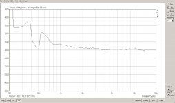
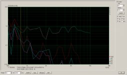
I would really appreciate some informed comment and analysis of my results! Working with both the DATs programme and ARTA I have created plots with FR(Pink), FR (Gated) and Phase, Group Delay and an Impedance and Phase graph of horn and driver combination.
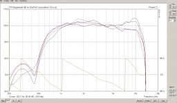
Briefly, the driver is the Beyma 750Ti, the single gated FR plots are a nest of curves taken at 0, 15, 30, 45 degrees horizontally at 1metre. These were in room so not exactly definitive but a number of samples were taken.
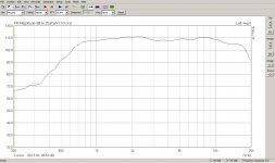
The crossover is set in DSP at 680Hz/24dB/oct/LR and "Thru" with EQ at 6dB/octave rising from around 3KHz up to 12KHz. The mic was the DBX which I have had good results from on a range of loudspeaker measuring tasks. I have also included a pink noise smoothed plot for interest.
Here are the plot results as attachments. I am less interested in comments regarding the FR plots as the anomalies and benefits of multicells in this department have often been published.
I am interested in what the Impedance/Phase/GD/FR+Phase plots indicate to those who understand the physics and their relevance to the horn's performance..in layman's terms please because I am not a physicist")
There's a gentleman in the UK who builds 10 and 15 cell multicell horns in his garage out of mdf..and sells them on e-bay. I took the plunge and purchased a pair of his 15 cell versions. Modelled on a truncated version of the Vitavox these horns have a cut of around 300Hz.
And they sound excellent but there is so little information out there on multicells I took the plunge and took my own measurements.
I would really appreciate some informed comment and analysis of my results! Working with both the DATs programme and ARTA I have created plots with FR(Pink), FR (Gated) and Phase, Group Delay and an Impedance and Phase graph of horn and driver combination.
Briefly, the driver is the Beyma 750Ti, the single gated FR plots are a nest of curves taken at 0, 15, 30, 45 degrees horizontally at 1metre. These were in room so not exactly definitive but a number of samples were taken.
The crossover is set in DSP at 680Hz/24dB/oct/LR and "Thru" with EQ at 6dB/octave rising from around 3KHz up to 12KHz. The mic was the DBX which I have had good results from on a range of loudspeaker measuring tasks. I have also included a pink noise smoothed plot for interest.
Here are the plot results as attachments. I am less interested in comments regarding the FR plots as the anomalies and benefits of multicells in this department have often been published.
I am interested in what the Impedance/Phase/GD/FR+Phase plots indicate to those who understand the physics and their relevance to the horn's performance..in layman's terms please because I am not a physicist
Attachments
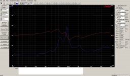
Ok! Yes, trying to get some idea I suppose as to the "load quality" of the horn and driver combination. For instance, except for the twin peak impedance spikes the rest looks quite benign....I have seen plots of horns with multiple resonant peaks. And is there anything revealed about the load that can be gleaned from the phase plots?
That kind of thing!!!
That kind of thing!!!
I think the phase plot looks pretty good, considering the complexity of the horn. My Altec multi cells may look worse, I'd have to check.
I don't know enough about what the horns reveal in the impedance plots to comment. For example, I couldn't look at you plot and say "Ah yes, bad loading here, good impedance there, etc." Probably someone here could.
The response looks darn nice for a 2" driver. The top end bump and roll-off may be from the thickness of were the cells join together - but I don't really know. The Altec cells are very thin back where they join near the throat. IIRC, the MDF horns walls are thicker at that point. Still, it looks pretty go for that size driver and horn.
The way I determine my high pass crossover point it to look at 2nd and 3rd harmonics and find the point at which they rapidly increase. I cross at least 1 octave above that. I figure the horn (or driver) is no good to me below that point.
Distortion?
Thanks Pano..but now you have opened a can of worms. I set about measuring the distortion today..my usual measuring set up, EMU sound card, USB2 to laptop/ARTA, analogue out on the sound card to a Mackie Mixer which then feeds the whole system by going to a A to D first then into the DSP set up. My usual system is all digital with only one final conversion to analogue to feed the power amps so any original analogue signal needs to be converted first. The mic is the DBX phantom powered by the little outboard Behringer power supply.
I must confess I am not sure how to calibrate the distortion levels created by ARTA because they vary depending on the gain setting of the impulse spike but I wanted to see the relative distortion.
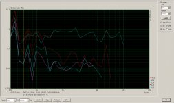
I was initially disappointed and confused by the results from the Multicells..to be honest they didn't make sense with a peak in distortion around 2Khz in 2nd, 3rd and 4th order.
I then measured the Faital 142 horn with the P Audio BM740 driver...this was measured at the mouth and at the 1m distance I had been recording the multicells at...bafflingly, same result with a distortion peak at 2Khz.
So not sure what I am measuring at all but I am assuming this distortion is "in the system" rather than the devices measured and I don't have the knowledge to find the culprit! Anyway, here are the plots....
Thanks Pano..but now you have opened a can of worms. I set about measuring the distortion today..my usual measuring set up, EMU sound card, USB2 to laptop/ARTA, analogue out on the sound card to a Mackie Mixer which then feeds the whole system by going to a A to D first then into the DSP set up. My usual system is all digital with only one final conversion to analogue to feed the power amps so any original analogue signal needs to be converted first. The mic is the DBX phantom powered by the little outboard Behringer power supply.
I must confess I am not sure how to calibrate the distortion levels created by ARTA because they vary depending on the gain setting of the impulse spike but I wanted to see the relative distortion.
I was initially disappointed and confused by the results from the Multicells..to be honest they didn't make sense with a peak in distortion around 2Khz in 2nd, 3rd and 4th order.
I then measured the Faital 142 horn with the P Audio BM740 driver...this was measured at the mouth and at the 1m distance I had been recording the multicells at...bafflingly, same result with a distortion peak at 2Khz.
So not sure what I am measuring at all but I am assuming this distortion is "in the system" rather than the devices measured and I don't have the knowledge to find the culprit! Anyway, here are the plots....
Attachments
Check this out:
http://profesional.beyma.com/pdf/CP750TiE.pdf
There is a distortion peak near 2 kHz too.
http://profesional.beyma.com/pdf/CP750TiE.pdf
There is a distortion peak near 2 kHz too.
Up date
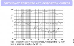
Lojzek, I know you have put a useful link to the Beyma driver but I am posting just the FR and distortion plot here. If this is compared to my plots there is no evidence of this huge peak around 2Khz. You will note again that this distortion increase is virtually identical to the P.Audio BM-740D/FaitalPro elliptical horn plot, which is very unlikely!
The other thing I may be missing of course, and this is where my lack of knowledge comes in, is the fact that a horn is a passive device..it has no active components at all but only effects the load the driver sees. I have read about compression effects in the throat, depending on it's diameter, which apparently increase distortion with increasing power. But my tests were well under 1 watt as these drivers are around 110dB/watt on these horns and I value my ears at my age...and there is no reason why it would appear at 2Khz and not much lower down the frequency spectrum?
So again I appeal to anyone out there who either knows their way around ARTA intimately or is a qualified acoustics or physics engineer to offer any advice or opinions...thanks!
Attachments
Take an impulse measurement, position the start gate before the impulse starts, and the end gate before the first major reflection. Post that image. Hit the 2fr button, put smoothing at 1/24. Lower the range to a 5dB scale. You will probably see issues in the response corresponding to most every blip in the impedance plot.
Thanks Dumptruck...these are gated but at 1/3rd octave smoothing. I am happy with the response plots as they were repeatable but obviously not at 1/24th octave resolution. I also ran them at 1/6th octave and the FR curves just had more small peaks/troughs of course but the trend remained the same. For setting up systems for listening distance rather than technical exercise I usually find 3rd and 1/6th are more than sufficient..after all you are not going to eq out every small peak and trough in the response anyway as that will vary substantially in different room locations?
But it did get me to research ARTA more!! I knew something was fundamentally wrong with my distortion plots so I thought reading the instructions might help...for goodness sake I have been using this programme for years now!
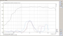
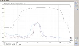
So apologies for any time wasted but I am pleased to be able to post two distortion plots (now done in "Steps") for the Faital Pro 142 Horn + P Audio BM740D and for the Multicell + Beyma 750Ti.
As I am still unable to calibrate the system in terms of true spl so I used a sound level meter with the mic at 1m distance from the horns, The level was adjusted until the tones reached the 100dB mark with C weighting. Crossovers remained in place and were set at 800Hz and 8Khz. I am pleased to see the Multicell with the bigger driver does have marginally better distortion content but both are a pleasant surprise.
It reinforces the opinion again that horns, despite their inherent high distortion, at normal and indeed way above normal domestic listening levels have low distortion content, superb dynamics and unparalleled dispersion control.
But it did get me to research ARTA more!! I knew something was fundamentally wrong with my distortion plots so I thought reading the instructions might help...for goodness sake I have been using this programme for years now!
So apologies for any time wasted but I am pleased to be able to post two distortion plots (now done in "Steps") for the Faital Pro 142 Horn + P Audio BM740D and for the Multicell + Beyma 750Ti.
As I am still unable to calibrate the system in terms of true spl so I used a sound level meter with the mic at 1m distance from the horns, The level was adjusted until the tones reached the 100dB mark with C weighting. Crossovers remained in place and were set at 800Hz and 8Khz. I am pleased to see the Multicell with the bigger driver does have marginally better distortion content but both are a pleasant surprise.
It reinforces the opinion again that horns, despite their inherent high distortion, at normal and indeed way above normal domestic listening levels have low distortion content, superb dynamics and unparalleled dispersion control.
Attachments
I will set it all up again tomorrow!! Probably be disappointed at 1/24th scale. I don't have a two channel system so I don't think I can benefit from the 2FR button?
I use the EMU 202 sound card but would need the EMU 404 or equivalent to run the two channel version, as I understand it. I was also going to do the burst decay and post that. I believe this to be quite a valuable plot in terms of looking for "nasties" as the impulse decays.
I have looked for months trawling the sites for multicell performance information and it just isn't out there. There may be some polar response information but I have never seen a full range of plots covering FR, impedance, phase and distortion. I appreciate one is measuring the specific driver as well but it does at least give some measured indication of how a last century concept and design can perform with modern drivers...?
Thanks again for the advice, getting there now and learning more about ARTA every day!
Thanks for the graphs. I wonder about the H2 so much higher than everything else. It should be highest, but looks out of proportion on your plots.
Have you ever used HOLMImpulse for measurement? Might be worth looking at its interpritation of distortion to see if it matched ARTA or STEPS.
And can you do a loop of your soundcard out, thru all devices and up to the amp input? I.E. the analog line level section. If you have some attenuation handy, you might be able to do a sweep of the amp output, so to have a look.
Thanks Pano......this is where I get a bit lost! I have the emu202 two channel outboard sound card running into a laptop with a usb2 connection.. I am not sure if I can do a "loop through" The analogue out runs from the sound card to a mackie mixer which feeds the digital rossovers etc. I adjust the system level with the output volume control on the mixer. Actually the distortion from this mixer is very low..
I would like ARTA to know what the spl is but I can"t see how to do it!!
I would like ARTA to know what the spl is but I can"t see how to do it!!
You could come out of the line level outputs (they are 1/4", right?) into the line level inputs. I doubt you'll see much distortion on the EMU. But you might want to try it with the Mackie in the loop just to be sure nothing is awry. The H2 may well be coming from the driver, the factory plots do show it fairly flat.
It's just nice to check the signal chain as much as possible to be sure all is working as it should.
It's just nice to check the signal chain as much as possible to be sure all is working as it should.
This is where I get confused! The emu does have 1/4" jack and stereo mini jack out....the mixer has all types of input.....1/4" mono jack in and tape in phono, etc. The output of the mixer goes to the rack...in detail, a tc electronic reverb which is used in bypass mode but as a A to D. The digital signal is then fed to a Behringer Ultramatch in up sampling mode only, 88.2khz/24bit. Here the digital signal outs go to two Ultracurves, one for global bass eq and the other for global mid/upper mid (horn) and bullet, An aes digital out signal is fed to two Alto stagedrive+ loudspeaker management systems, aes in. This gives me the eight channels of dsp I need to control the 8 channels of amps. In band eq/delays/crossover s are dealt with by the Alto's. The amps are pro rack mounts....and nothing esoteric. A chunky Inter R for bass, 4 mono bridged Samson 120's for mids and horns and a Temple Audio Bantam for the Visaton Super Tweeters. The Samson 120 is the biggest surprise sounding clean, uncoloured and open. The little Temple Audio is fast, clean and open. I have kept the latency of the system the same throughout both processing routes and with digital sources only one D to A conversion stage right at the end with the Alto's.
So, yes, I am seeing the distortion of the whole system .
I could come out of the mixer just into the Temple Bantam ( .007% THD) and rerun the tests but the horn drivers should be protected by crossovers at lf....or is this dealt with in ARTA by setting the lf point?
Having said all that I am still confused as to how to loop connect the emu/mixer/laptop and what it is I am calibrating!!
- Status
- This old topic is closed. If you want to reopen this topic, contact a moderator using the "Report Post" button.
- Home
- Loudspeakers
- Multi-Way
- Multicell Performance Help!