Re: The Mullard faked!
This cap is there, 330pF actually. On this specific amp., it is just the extra OT , else exactly same as org. Mullard 5-20.
Tube_Dude said:See if across the feedback resistor exist a capacitor of 100pF...if not ...put one...and keep as informed!
This cap is there, 330pF actually. On this specific amp., it is just the extra OT , else exactly same as org. Mullard 5-20.
Tube_Dude said:And the value of the feedback resistor?
For 8ohm speakers, (7.5 on the org. schematic) Mullard recommend 5.6k for feedback resitor, mine is 5.6k.
all of it beguin with more 10% in heater voltage!
Try to change the capacitor to 220pF and see in a scop if the oscilation increase or became smaler...
But i'm a litle ceptical as the diyer that assembled your amp may have comected same mistakes...and seeing it oscilating put the rc at the anodes of the EL34 for trying to stop the oscilation... that it still have!
Jorge
Re: Re: The Mullard faked!
And as I said earlier, R24 and 25 goes directly to centretap on T1.
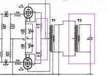
Why would there be 2 OT's ?
Anybody know of software with tube symbols?
JDeV said:On this specific amp., it is just the extra OT , else exactly same as org. Mullard 5-20.
And as I said earlier, R24 and 25 goes directly to centretap on T1.
Why would there be 2 OT's ?
Anybody know of software with tube symbols?
Attachments
Importance??
How importand is the following , from this article:
"Design for a 20-Watt High Quality Amplifier
By W.A. Ferguson,* B.Sc.(Eng), A.C.G.I., Grad. I.E.E.
"Choice of Valves and Operating Conditions"
* Mullard Valve Measurement and Application Laboratory.
"A bus-bar earth return has been used with chassis connection at the input socket
I know my amp's earth busbar is only connected to the chassis near the bridge diodes.
The Great Transfomer Scandal
JDev,
I'd hazard a guess that perhaps the first transformer has a relatively high output impedence - perhaps it was designed for a 70 volt line - and thus another transformer is required to drop the output for normal speakers. Of course, the second output tranny is not included in the feedback loop and this will affect the linearity of the response (apart from any mismatch on impedences by this setup).
There is another difference also - the first tranny is set up for normal loading, not UL (distributed loading) of the original Mullard, and that means the cathode bias resistors are wrong, too high really for this kind of working. If you want to sort out any instability you'd need to sort these things before worrying about bus bar connections.
(If all else fails to remove the oscillation, try small caps, a few hundred pfs from each of the EL34 grids to ground, or small caps, 1000pf at 1500vdc working, from each of the EL34 anodes to the centre tap of the first transformer. If the amp is deviating from the original Mullard 5-20 circuit then you cannot guarantee that the same methods used in the original will bring stability to your amp).
Sweet music
Thanx to all for help. Bournville, you did it.
1st tried the "small caps to ground" idea. no help.
So disconnect OT2, problem gone. Connect fat 8ohm resistor, inject 100Hz test signal, appears perfect on scope. Pump up volume, start clipping at 2.4Vrms. So atleast it is working, no I must just get it up to the claimed 20Watts.
What must I do next to increase the output. At 12ohm I got it up till 4.2Vrms, still not 20Watt. Is it all because of the wrong OT, or some other factors as well?
transformers... transformers....
Jdev,
Glad that you've got the oscillation under control, although I can't claim any credit for it!
It is interesting that the output appears to increase with a higher load. Looking back on the altered circuit, I was thinking that perhaps your Mullard had been adapted for PA work rather than normal audio work, which could mean that perhaps the transformer secondary has quite a high impedence (sometimes as much as 500 ohms) because PA speakers often have their own output transformers connected. Likewise, the normal loading as opposed to UL working could be an attempt to increase output at the expense of distortion, not such a problem in a PA amplifier.
In terms of checking, are you are sure of the HT voltage, bias voltage on the EL34 cathodes (check to make sure that operating conditions are not upset by 'leaky' coupling caps) and efficiency of the GZ34? Check the resistance of the output winding of the transformer - is it higher than you'd normally expect for a 3, 8 or 15 ohm secondary? If it is significantly higher it may be the high secondary of a PA transformer, which is why another transformer is connected to bring it down to 3 or 8 ohms.
If it does seem to be a 500 ohm secondary, check the feedback resistor - if it is a value for a 8 or 15 ohm secondary it will be way to low for a high impedence secondary, which would cause phase shift and oscillation in the amp.
At this moment I 1st enjoy some music on it before I dig further. I just experienced a weird thing. I connected a speaker to the amp, switched it on without a source, and suddenly I could here the local radio station through the speaker. quit load as well. How can this be?
I did the same with other amp, but not stereo radio now. When I connect 2 amps chassis to each other, all radio disappeared. (Secret Mullard amp/reciever??)
Something else I do not understand, when I previously tested MOSFET amp and Gainclone for max power output, I connected 8ohm load, feed 100Hz sine wave and see when it start clipping. I then measured with TRM multimeter got V, then P=V*V/R = Pmax
Is this normally correct? When I did this with tube amp, I got V=2.4V, R=8ohm , Pmax=0.72Watt
If it is even 1Watt, why does it sound so loud at this level, compared to other amps? I also hear some hum when no source is on, is this groundloop problem or could it be from elsewhere maybe?
Last questions. What should the exact primary and secondary ohms be for the OT for 8ohm load and why can I not get more power out of this amp?
I did the same with other amp, but not stereo radio now. When I connect 2 amps chassis to each other, all radio disappeared.
(Secret Mullard amp/reciever??)Something else I do not understand, when I previously tested MOSFET amp and Gainclone for max power output, I connected 8ohm load, feed 100Hz sine wave and see when it start clipping. I then measured with TRM multimeter got V, then P=V*V/R = Pmax
Is this normally correct? When I did this with tube amp, I got V=2.4V, R=8ohm , Pmax=0.72Watt
If it is even 1Watt, why does it sound so loud at this level, compared to other amps? I also hear some hum when no source is on, is this groundloop problem or could it be from elsewhere maybe?
Last questions. What should the exact primary and secondary ohms be for the OT for 8ohm load and why can I not get more power out of this amp?
It looks as though you are going to have to check these amplifiers carefully. Still, they were a bargain, so a little bit of detective work is reasonable.
First, trace out the circuit to see if it is the same as a Mullard 5-20. If there are changes, it could be that someone who didn't know what they were doing has modified the amplifiers.
Having checked the circuit, measure all the voltages and mark them on the diagram. Then compare them to the theoretical voltages. 5% error is fine, but 10% might indicate a problem.
Are both amplifiers the same? If not, then you are probably looking for genuine component faults.
Likely faulty components are (most likely first):
Leaky coupling capacitors
Leaky electrolytics
Tired valves
Carbon resistors "gone high" in value
Good luck.
EC8010 said:Having checked the circuit, measure all the voltages and mark them on the diagram. Then compare them to the theoretical voltages. 5% error is fine, but 10% might indicate a problem.
O.K. I think I sorted out the impedance problem with the 2 OT's. The 2nd OT consists of 4 x 8.7ohm windings and a 1.2ohm winding. By useing 2 x 8.7 windings in serie, I got the impedance ratio to 5200:8 for the 2 OT's combined. (parrallel) The 1st OT got a ratio of 128:8 and the org. combined ratio was 22500:8


Now I can atleast go to about 18Watt before clipping occur's. Only other problem is loud hum all the time.
I also took some measurements, both amps about the same, but am not sure what theoratical values must be in order to compare. I traced the circuit, and except for 2 silicone diodes in place of GZ34, and the OT thing, it is exactly as Mullard 5-20, same component values. The OT do not have 33% taps , so G2 of EL34 now goes to 1k resistor and then to centretap and back to +Can somebody please check these values and comment on them?
What can cause the hum, I do I cancel it?
Measured values:
Attachments
Your HT leaving the power supply is a little low (390V as opposed to 433V specified by Mullard), which is why you don't get quite as much power as Mullard. Otherwise your voltages seem consistent.
You could probably obtain a bit more HT by increasing the value of the first smoothing capacitor beyond 22uF. If you do a search, and look for "Duncanamps" you will find a piece of freeware called Power Supply Designer. Using this, you will be able to simulate the effect of increasing the reservoir capacitor, although PSUD tends to be a bit pessimistic in practice. It is worth restoring the HT to 433V because the design will then be working optimally. If you do increase the reservoir capacitor, choose one with a high ripple current rating, fit soft recovery diodes, and add a negative temperature coefficient thermistor in series with the mains to limit the inrush current.
Is the hum 100Hz or 50Hz? 100Hz almost certainly comes from the power supply, 50Hz from poor earthing.
EC8010 said:Is the hum 100Hz or 50Hz? 100Hz almost certainly comes from the power supply, 50Hz from poor earthing.
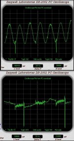
The hum is 50Hz, see attached pic.
I found this circuit with voltages indicated, just now. According to this 1, the voltages are as follows:
EF86 anode=2.2V
12AX7 g1=82V, g2=85V, a1=325, a2=325V
On mine:
EF86 anode=0.8
12AX7 g1=138V, g2=106V, a1=182V, a2=232V
Knowing my supply is less, mine is not "balanced" and EF86 anode v quit low.
Are these problems or O.K.
Hum and sine 200Hz:
(Pictures From this software, very nice. http://www.dazyweblabs.com/shannonsoft/page3.html )
Attachments
Re anode voltage imbalance: You might want to look at the 180k anode loads to check that they are the corrcet value. I don't know what you mean by an anode voltage of 2.2V, perhaps you actually mean cathode. In which case, the EF86 could be tired.
Hum has to be measured in the absence of signal. If it's 50Hz, try powering up just one amplifier into a loudspeaker. Does it hum? Is the 0V rail connected to chassis (which should be connected to mains earth)? I'm afraid there are lots of things that can cause hum, and it takes too long to detail them here. If you have a digital camera and can post shots of the internals, this might help.
Hum has to be measured in the absence of signal. If it's 50Hz, try powering up just one amplifier into a loudspeaker. Does it hum? Is the 0V rail connected to chassis (which should be connected to mains earth)? I'm afraid there are lots of things that can cause hum, and it takes too long to detail them here. If you have a digital camera and can post shots of the internals, this might help.
EC8010 said:Re anode voltage imbalance: You might want to look at the 180k anode loads to check that they are the corrcet value. I don't know what you mean by an anode voltage of 2.2V, perhaps you actually mean cathode. In which case, the EF86 could be tired.
 You're quit right, Cathode that is, and it isn't just tired , it actually went to sleep now and snores like hell. I notice earlier that Kv (cathode voltage) became less as the day went by. Even if I fit other 1 it also snores (from yesterday already) Somehow they got damaged with me trying to get the amps working, are they quit sensitive ??
  "Handle with care !!! EF86 got MOSFET DNA "
 Me also start draw high current now, maybe also tired, must go sleep, will dream - tube, tube, tube, tube.........
While I am waiting for the correct OT's , I want to make my amps more "efficient" or shall I say easier on the tubes. Since the org. circuit (as on page 1 of this thread) use 440V - after choke - and mine only got 390V, which components should I change and to what values?
What can cause the EF86 to go faulty? I lost 2 already and did not really do much to circuit else then adjusting the OT to more or less the correct ratio of 5k:8 - was 22500:8. All components test exactly as per org. circuit values. I know that I can not expect to still get 20W from them, but want to make sure they run within exceptable limits. For exact voltages on them now, see above circuit.
What can cause the EF86 to go faulty? I lost 2 already and did not really do much to circuit else then adjusting the OT to more or less the correct ratio of 5k:8 - was 22500:8. All components test exactly as per org. circuit values. I know that I can not expect to still get 20W from them, but want to make sure they run within exceptable limits. For exact voltages on them now, see above circuit.
Amp modifications...
JDev,
I'm not quite sure about what you mean by 'efficient' and 'easy on the valves' - making a circuit easy on the valves will not necessarily be efficient in increasing output!
However, given that the output of the amp is set up for normal distribution rather than ultra-linear and the voltage is low by about 50 volts, then both the EL34 screen resistors and cathode bias resistors are a little high in value. According to my manual with an anode voltage of 375, the EL34 should have a screen resistor of 470 ohms and a cathode bias resistor of 260 ohms in normal distribution mode. As yours is nearer 390 volts HT if you reduce the screen resistors to about 600 ohms and the cathode resistors to 300 ohms, you should still be slightly under-running the valves whilst increasing output. You may find that this also provides a better match to your output transformer.
Make sure that the power supply can handle the HT current - in UL operation EL34s take considerably less HT current than in normal distribution, and with four EL34s in your stereo amp the difference will be quite significant.
I've no idea why you are losing EF86s though!
Hi,
Cheers,
I'll bet it's the EF86 anode resistor changing value!I've no idea why you are losing EF86s though!
Cheers,
- Status
- This old topic is closed. If you want to reopen this topic, contact a moderator using the "Report Post" button.
- Home
- Amplifiers
- Tubes / Valves
- Mullard 5-20