I'm doing LTSpice simulations for Mullard 5-20 (which I'm planning to build), and I'm wondering how well original cathode bias would work in real life. Would there be a need to change the design to adjustable bias?
In the original schematics there are 470ohm resistor and 50uF capacitor in parallel. This gives Va around 370-380V and Ik = 61mA. Would this be little bit too much for EL34? And would it be a good idea to increase the capacitor to 100uF or 220uF?
In the original schematics there are 470ohm resistor and 50uF capacitor in parallel. This gives Va around 370-380V and Ik = 61mA. Would this be little bit too much for EL34? And would it be a good idea to increase the capacitor to 100uF or 220uF?
In my 5-20 builds I used the original design and it worked out perfect for me. I think it's more like 400 volts at the plate compared to cathode.
Don't forget the cathode current includes the screen current, and it does end up running at about max rated plate dissipation for an EL34.
Don't forget the cathode current includes the screen current, and it does end up running at about max rated plate dissipation for an EL34.
Cathode resistor bias needs to run the valve at the dissipation limit so that it can still give a good result for full power sine wave testing, when the bias will have shifted due to second-order distortion. If you only listen to music, not sine waves, then you can run the valve slightly cooler. The Mullard book gives this as an alternative for the EL84 amp, but not EL34.
Alternatively, do what I did and use a mixture of fixed and cathode resistor bias. I run mine at about 55mA cathode current.
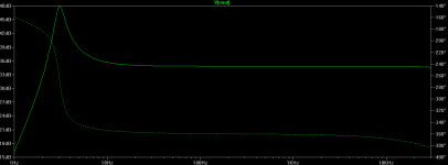
The capacitor value affects LF phase shift, so can affect LF/subsonic stability. You may be able to see this in your simulations. Look in the region 2-20Hz for changes in closed-loop frequency response.
Alternatively, do what I did and use a mixture of fixed and cathode resistor bias. I run mine at about 55mA cathode current.
The capacitor value affects LF phase shift, so can affect LF/subsonic stability. You may be able to see this in your simulations. Look in the region 2-20Hz for changes in closed-loop frequency response.
I'm doing LTSpice simulations for Mullard 5-20 (which I'm planning to build), and I'm wondering how well original cathode bias would work in real life. Would there be a need to change the design to adjustable bias?
In the original schematics there are 470ohm resistor and 50uF capacitor in parallel. This gives Va around 370-380V and Ik = 61mA. Would this be little bit too much for EL34? And would it be a good idea to increase the capacitor to 100uF or 220uF?
show us your schematic and LTspice simulation files please
An externally hosted image should be here but it was not working when we last tested it.
No. The feedback loop will just adjust the driver from the LTP to accomodate the change. If the OPT is inadequate then the solution is to restrict the LF going in.JonSnell Electronic said:Increasing the C value will make the valve work too hard at lower order frequencies that the output transformer cannot usefully use. It will just saturate the transformer and waste energy.
Increasing the cathode cap will reduce the work done by the LTP so may slightly reduce LF distortion.
show us your schematic and LTspice simulation files please
Actually now I notice, that I had only 400V supply in my simulations instead of original 440V supply.
Anyway, here is the schematics with 440V supply. The actualy supply (GZ34, choke etc.) is not included.
This uses norman koren library. The transformer is supposed to be Hammond 1650H.
The frequency response also seems to have interesting thing at low frequencys (see the attached png). Should this be normal for 5-20?
Attachments
Alternatively, do what I did and use a mixture of fixed and cathode resistor bias. I run mine at about 55mA cathode current.
What plate voltage you have when you are running it 55mA?
The Mullard book shows a small subsonic ripple, so they presumably knew they were pushing at the boundary of LF stability.
You will find if you change the cathode cap value you can adjust the peak. Also vary coupling cap values. You need to ensure that the various LF time constants do not coincide. One which people often forget is the LTP second grid AC ground - R10,C6 in the circuit shown in post 6.
I had 400-420V on the main supply rail.
Last edited:
I found that the optimal capacitor value is better adjusted on test, because it depends on the transformer. Connect the scope (DC coupling) to one cathode snd weep the low frequencies and try to have a balance between ripple (lower C gives more) and DC bias shift (more C gives more, at higher power output) , at various power levels. Then you decide how low will you filter the low frequencies going in the amplifier, as DF96 said.
Alternatively, do what I did and use a mixture of fixed and cathode resistor bias. I run mine at about 55mA cathode current.
I run mine on cathode bias at around 100mA.
Its a while since I designed it so not sure where 180R cathode resistor value came from.
I run mine on cathode bias at around 100mA.
Its a while since I designed it so not sure where 180R cathode resistor value came from.
Is that common bias resistor for two tubes? Or for a single tube
 ?
?Is that common bias resistor for two tubes? Or for a single tube
Well spotted, its one 180R resistor for two cathodes.
Well spotted, its one 180R resistor for two cathodes.
I know some people that like to abuse tubes but I figured 100mA is a bit much for just one EL34, unless melting plates is your thing. From what I have read on here tubelab likes to blow tubes up.

I know some people that like to abuse tubes but I figured 100mA is a bit much for just one EL34, unless melting plates is your thing. From what I have read on here tubelab likes to blow tubes up.
When I first built the amp I powered it up to test it.
One of the output valves glowed bright red (the heater looked ok).
Turned out I completely missed a grid stopper resistor for that valve and the valve was passing max current.
When I first built the amp I powered it up to test it.
One of the output valves glowed bright red (the heater looked ok).
Turned out I completely missed a grid stopper resistor for that valve and the valve was passing max current.
The grid stopper I believe is only there to prevent oscillation. So I believe the grid leak resistor is what you are referring to.
Glowing plates are bad

The grid stopper I believe is only there to prevent oscillation. So I believe the grid leak resistor is what you are referring to.
Glowing plates are bad
No the grid stopper was missing meaning there was no path to zero volts via the grid leak resistor.
I put the grid stopper resistor after the grid leak resistor.
I noticed pretty quick it was glowing and turned it off.
No the grid stopper was missing meaning there was no path to zero volts via the grid leak resistor.
I put the grid stopper resistor after the grid leak resistor.
I noticed pretty quick it was glowing and turned it off.
I get it now sorry for the confusion.
I had a friend whom invited me over and he had just replaced his output power tubes with a quad of NOS RCA metal base 6550's. Upon entering his living room I noticed this "smell", and yeah I know that "smell" of a tube that's been red plating for a while and somehow not failed. But anyway I looked at his stereo and saw the poor tube glowing cherry red. I don't know how long it was like that for but it didn't fail. Turns out the sockets were of poor quality and broke, basically the tube pins pushed the female part of the socket out the back of the tube socket and caused intermittent operation, pin 5 had no connection.
- Status
- This old topic is closed. If you want to reopen this topic, contact a moderator using the "Report Post" button.
- Home
- Amplifiers
- Tubes / Valves
- Mullard 5-20 EL34 biasing