Re: QQ.
Hmm,
Isn't that called "enhanced triode"? As done by our friend Tim de P, with EL509's?
What'll the gain be?
")
fdegrove said:Hi,
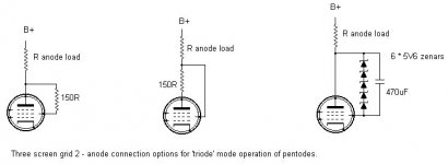
Now if we were to tie screengrid and control grid together, would that approach true triode operation?
As opposed to the psuedo triode mode operation as in the third figure posted.
Cheers,
Hmm,
Isn't that called "enhanced triode"? As done by our friend Tim de P, with EL509's?
What'll the gain be?
Re:QQ.
Hi,
If memory serves me correctly than Tim actually drives the EL509 from the screengrid...can't remember what he did with the controlgrid though.
I'll check it out.
Cheers,
EDIT: he ties this grid to the cathode.
Hi,
Isn't that called "enhanced triode"? As done by our friend Tim de P, with EL509's?
If memory serves me correctly than Tim actually drives the EL509 from the screengrid...can't remember what he did with the controlgrid though.
I'll check it out.
Cheers,
EDIT: he ties this grid to the cathode.
hmm everyone seems to have a different view on this pentode/triode setup. as far as i remember isnt a pentode tube in triode mode when the screen and suppressor are tied to the anode? and in pentode mode when suppressor is tied to cathode and screen to anode? thats how i remember it. also, the point of pentode is to increase the signal and decrease distortion from electrons rebounding of the anode; the screen being tied to the plate accelerates the electrons more, while the suppressor being tied to the cathode slows them down enoug that they would not rebound of the plate due to high speed/impact force which would cause distortion. my two cents. where's tim (sch3matic) when you need him?..
mig-ru said:isnt a pentode tube in triode mode when the screen and suppressor are tied to the anode?
No.
...and in pentode mode when suppressor is tied to cathode and screen to anode? thats how i remember it.
Nope. This is wrong too.
See my diagrams above. They are correct. I don't see what's so confusing about this.
Ok time to clarify. (Sigh.)
A pentode tube has three grids. You can do whatever the hell you want with these, but best results of course come from proper usage.
Generally, the grid (g1) is used for primary signal input. Screen (g2 - WTH is sg2? screen grid 2???) is used either as a 'false plate' (which electrostatically seperates the grid-cathode area from the plate proper, allowing a high plate current at low plate voltages, and also a high plate resistance), or as a minor - and, it should be noted, nonlinear* - point of signal input. The suppressor grid (g3) may be tied to cathode internally, and might consist of a full-blown wire grid, or simply two beam-focusing plates either side of the electrode structure inside the plate, to increase electron density (I won't go into those details at this time). In the latter case, the tube becomes known as a beam tetrode, as the beam plates are almost always connected to cathode internally.
*The screen *is* a linear input, as screen-modulated AM transmitters can attest to. However, when moving in sync with the plate (as triode), the NFB effect it produces is nonlinear according to a 3/2 square law or so; hence, NFB applied in this was is not as effective as other, externally-applied NFB.
Anyway. With the signal applied to g1, screen connected to a constant-voltage supply, and a load on the plate, the tube is said to be in pentode mode.
If a fraction (1 to 99%) of the plate's voltage is impressed upon the screen grid, it is said to be in ultralinear (UL) mode.
If the amount of plate voltage applied to the screen is equal (i.e. 100% UL), it is said to be in triode mode.
In an earlier post, someone noted that screen current might be higher in triode mode. This is clearly false; if the tube is rated for triode mode (especially in harsh conditions such as a vertical deflection amplifier), you'd think the manufacturers would have thought of this and altered the design to keep it within limits.
And lastly, no significant signal power comes of the screen grid, in triode or UL mode. It acts more as an input.
Tim (trying not to sound impatient of pedantic, just tired of reading false information on what should be a hard science, espcially by now. Hey, if anyone wants to clear up anything tubed, I'd be glad to discuss it with you.)
Re: ...life is simple - valves aren't...
A post from the JoeList on this topic:
dave
James D. said:2) with sg2 and the anode at the same potential and sg2 seeing the electron flow first, sg2 has a tendency to act as the anode itself and hence a relatively high current can flow through sg2 shortening its life. This can be overcome by introducing a small voltage offset between the anode and sg2, bypassed by the signal. Typically 30Volts is an effective voltage offset that causes almost all the current to flow through to the plate.
A post from the JoeList on this topic:
The way I do this little trick - as a couple of folks already knew - is
to bypass a zener with a cap. But, not just any zener and not just any cap.
My favorite zener is a 1N821, a 15cent, 1/2 watt, 6.2 volt part that is
both very quiet and of nearly zero tempco. I forget why 6.2V is the "magic"
voltage for zeners but it is, the noise falls thru the floor and the low
tempco yields a very stable voltage source . Maybe someone could post on
this 6.2V business . . .
To build this:
- string 5 of the 1N821s in series and set them aside.
- take two, 16V, 470uF Sanyo OSCon caps and put a 10k resistor across
each one, then hook the two RC combos in series; then connect that
assy. across the zener string being sure to observe the polarity.
- then put a ten ohm, one quarter watt resistor on the cathode end of
the string and a resistive ferrite bead on the other.
- connect the other end of the ten ohm resistor to the plate of the
tube to be "triode connected" and the ferrite end of the assembly
to the screen, and there you have it.
Note that if you are using true, three grid EL34s that the suppressor
is best connected to about -5V or so. Just voltage divide off your bias
supply.
Biasing that grid slightly negative reduces its electron interception to
essentially zero.
Have fun discovering what a triode connected tetrode/pentode really
sounds like.
Bill - PEARL, Inc.
dave
Sch3mat1c said:Ok time to clarify. (Sigh.)
...If a fraction (1 to 99%) of the plate's voltage is impressed upon the screen grid, it is said to be in ultralinear (UL) mode....
Tim, I'm sorry to say but, (sigh) alas your answer is partially incorrect.
Ultra-linear is, in fact, a specific point of low impedence supply to the screen. It can be found experimentally by locating the point where lowest THD and output impedence meet highest power output. In general, as I said, this is roughly 43% of the primary plate winding.See David Hafler's article from Audio Engineering for clarification.
Joel (just trying to clear up, for a second time, info which is readily available.)
Blumlein
Although Hafler and Keroes coined the term "ultra-linear" in 1951, the technique of tapping a voltage for the screen grid of "between about a quarter and a half of the voltage swing on the anode" was patented by Alan Dower Blumlein in 1938 (UK patent number 496,883).
Although Hafler and Keroes coined the term "ultra-linear" in 1951, the technique of tapping a voltage for the screen grid of "between about a quarter and a half of the voltage swing on the anode" was patented by Alan Dower Blumlein in 1938 (UK patent number 496,883).
The 43% isn't perfect, BTW, it's just the most commonly used point. The best depends on desired characteristics, tube type, and operating point. 43% is probably best for 6L6 and EL34, I forget.
Patrick Turner of Turner Audio says up to 60% for some situations, or sometimes as low as 20%.
Tim
Patrick Turner of Turner Audio says up to 60% for some situations, or sometimes as low as 20%.
Tim

- Status
- This old topic is closed. If you want to reopen this topic, contact a moderator using the "Report Post" button.
- Home
- Amplifiers
- Tubes / Valves
- Mullard 3-3