Yeah, had them clamped.
No I haven't soldered the rca's yet, will do that now.
With two fets in the output I can get 8.8Vrms on the output. Prior was ~2.5Vrms, it seems the protection circuit is kicking in. I will throw two more outputs in and see what happens.
With 4 fets I am back to ~2.5Vrms, arghh.
No I haven't soldered the rca's yet, will do that now.
With two fets in the output I can get 8.8Vrms on the output. Prior was ~2.5Vrms, it seems the protection circuit is kicking in. I will throw two more outputs in and see what happens.
With 4 fets I am back to ~2.5Vrms, arghh.
Last edited:
The source leg of the high side FET should be connected to the positive speaker terminals. Confirm that this is the case.
If that is true and you had the ch2 probe on the source leg of the high side FET, you would have negative rail voltage on the positive speaker terminal. If the voltage on the source leg of the high side FET is at the negative rail, the voltage across the speaker terminals should be equal to the rail voltage (unless the connection between the FET and the speaker terminals, via the inductor, is open).
Is ti possible you uploaded the wrong photo?
High side fet:
S,Pos speaker terminal
D,Pos rail
G,Drive signal
Low side fet:
S,Neg rail
D,Neg speaker terminal
G,Drive signal
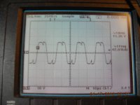
Pic 1 shows the low side fet, the equivilant pic would be from gate to drain on the high side fet. If that is true, the gate signal will show no offset. While the drain would be at ~50V.
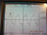
Picture show high side channel 1 on gate and channel 2 on drain.
S,Pos speaker terminal
D,Pos rail
G,Drive signal
Low side fet:
S,Neg rail
D,Neg speaker terminal
G,Drive signal
Pic 1 shows the low side fet, the equivilant pic would be from gate to drain on the high side fet. If that is true, the gate signal will show no offset. While the drain would be at ~50V.
Picture show high side channel 1 on gate and channel 2 on drain.
Attachments
Last edited:
I have this same amp in the wifes car, It may have to come out to compare some signals.
I can ramp the gain until the input clips when no output fets are present. It seems to be a problem in a shutdown circuit or current sense. The only other oddity is a LM311 that has -50V on pin4 and -38V on pin 8. Not sure what that means, but the datasheet states a total of 36V supply. I thought this to be the differential between + and - supply.
Ramblings....
The 311 is sitting on the negative rail. It's used to sense the voltage across the low side source resistors for over-current protection. It's likely using a 12v Zener diode to regulate the supply voltage. That seems to be OK. If the 0.22 ohm source resistors are within tolerance and the over-current protection is being triggered, it's likely doing so because there's a fault causing too much current to flow through the outputs.
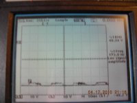
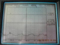
Could the 494 IC be damaged? Attached is the waveform for 8 and 11 on my good amp. I replaced one of the A56's with a leaded 3906 to see if my waveform would clear up and there was no change. That kind of points me back to the IC, thought these were pretty robust.
cory
cory
Attachments
The waveforms I posted were from a working amp and the waveform from your amp were very similar. It's possible that the 494 could be damaged but I see no evidence of it.
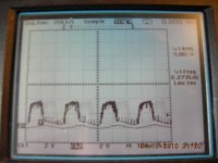
Check the waveform on your wife's amp before the end of the mute delay (before the outputs start oscillating). It's likely to be identical to yours.
Check the waveform on your wife's amp before the end of the mute delay (before the outputs start oscillating). It's likely to be identical to yours.
- Status
- This old topic is closed. If you want to reopen this topic, contact a moderator using the "Report Post" button.
- Home
- General Interest
- Car Audio
- MTX 421D supply issue