GeWa said:Russ,
When feeding the Opus DAC with a "Low Current Dual Power Supply", am I right that a transformer with dual 0-9V secondaries is sufficient enough. The LCDPS needs to be set at 5V and 7,5V so I don't see a point of using a transformer with 15V secondaries. With 9V (x1.412) the voltage regulators will run a lot cooler I guess.
Regards
Absolutely, 9V secondaries are fine. We supply the 15V just so that we only have to stock one type. The extra drop does not hurt a thing, and everything will stay nice an cool either way.
:EDIT: Hah Brian beat me. :EDIT:
Cheers!
Russ

Hi Russ, you guys seem very busy as I haven't received a reply on my mails. Is there still a beta PCB left or can I order the new Opus PCB ? I could do with a beta PCB without the receiver.
My Opus is not bass shy anymore after replacing the 10k resistor in the input circuitry for a 100 Ohm resistor. I don't have an explanation for the change in sound, maybe the caps broke in or fill in .... ( any other vague audiophile reason )")
I am very pleased with the results but the static clicks have not disappeared entirely. I guess my Philips Streamium is the cause as other cdplayers don't exhibit the same phenomenon. My design for a PCB for a passive output stage has been delivered to a board house. When they're finished I will report how they sound.
My Opus is not bass shy anymore after replacing the 10k resistor in the input circuitry for a 100 Ohm resistor. I don't have an explanation for the change in sound, maybe the caps broke in or fill in .... ( any other vague audiophile reason )
I am very pleased with the results but the static clicks have not disappeared entirely. I guess my Philips Streamium is the cause as other cdplayers don't exhibit the same phenomenon. My design for a PCB for a passive output stage has been delivered to a board house. When they're finished I will report how they sound.
jean-paul said:Hi Russ, you guys seem very busy as I haven't received a reply on my mails. Is there still a beta PCB left or can I order the new Opus PCB ? I could do with a beta PCB without the receiver.
My Opus is not bass shy anymore after mods to the input circuitry. I am very pleased with the results. My design for a PCB for a passive output stage have been delivered to a board house. When they're finished I will report how they sound.
Hello JP,
Very sorry, I must have either missed your email, or my spam filter caught it. Very sorry.
No I don't think we have any of the beta boards anymore. But we have plenty of the new boards.
I am excited to hear about your passive (transformer correct?) output stage. It should be very interesting, and a nice option for those who want that.
Cheers!
Russ
My Opus is not bass shy anymore after mods to the input circuitry.
Mods??

Regards
GeWa said:
Mods??
Regards
He is talking about the SPDIF input transformer on the beta boards. There was an early issue with resistor values.
Cheers!
Russ
jean-paul said:OK, but when I want to order on the website it says "out of stock" .......
Ah... that was a mistake on our part, we ran out of some parts but all of the boards are still available. You should be able to order them now.
Cheers!
Russ
Hey,
I'm having hard times trying to get my opus working :\
The spdif board got good signal(all the led are green),
And the seems that the voltage is OK(I've measured 7.5v across VD and VA and about 5V across DVDD and AVDD on the chip)
For now I'm using the O+ and OG, and hearing no sound but a faint "thump" when I'm powering up/down the dac.
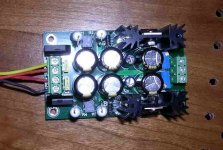
I've probably got the switches wrong, so here are the boards:
DAC Board
SPDIF Board
(sorry about the huge images...)
Thanks in advance.
I'm having hard times trying to get my opus working :\
The spdif board got good signal(all the led are green),
And the seems that the voltage is OK(I've measured 7.5v across VD and VA and about 5V across DVDD and AVDD on the chip)
For now I'm using the O+ and OG, and hearing no sound but a faint "thump" when I'm powering up/down the dac.
I've probably got the switches wrong, so here are the boards:
DAC Board
SPDIF Board
(sorry about the huge images...)
Thanks in advance.
SoapSeller said:Hey,
I'm having hard times trying to get my opus working :\
The spdif board got good signal(all the led are green),
And the seems that the voltage is OK(I've measured 7.5v across VD and VA and about 5V across DVDD and AVDD on the chip)
For now I'm using the O+ and OG, and hearing no sound but a faint "thump" when I'm powering up/down the dac.
I've probably got the switches wrong, so here are the boards:
DAC Board
SPDIF Board
(sorry about the huge images...)
Thanks in advance.
Set IWO high, and remove the jumpers on RSTB,ZERO,DIFFHW,M8X.
See what happens then.
Cheers!
Russ
SoapSeller said:Got sound!
I've tried the IWO before, but I didn't realized that there is a different between no jumper and low.
Thanks Russ!
Very good.
Your certainly welcome.
The bigger problem was that RSTB was low.
That is the reset pin. But IWO should be high also because the output of your SPDIF module is 24bit.Cheers!
Russ
Having issues with LCBPS for Balsie
Guys,
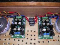
I'm finishing up the assembly of my DAC and I was checking out the power supplies before I hooked anything else up. The LCDPS for the reciever and DAC modules looks fine and I had no trouble adjusting the output to 7.5 VDC using the pots. However the LDBPS for the balsie doesn't seem to be resopnding to the pot adjustments. On the tranfo inputs I'm reading 17.2 VAC across the blk & red, and across the yellow & orange feeds to the PS. On the LCBPS outlets I'm reading -20.6 VDC and 21.3 VDC between the gnd and - & + terminals. Adjusting the pots does nothing at all. I've included some pics of the hookups. What do you think I'm doing wrong?
Thanks
PJN
Guys,
I'm finishing up the assembly of my DAC and I was checking out the power supplies before I hooked anything else up. The LCDPS for the reciever and DAC modules looks fine and I had no trouble adjusting the output to 7.5 VDC using the pots. However the LDBPS for the balsie doesn't seem to be resopnding to the pot adjustments. On the tranfo inputs I'm reading 17.2 VAC across the blk & red, and across the yellow & orange feeds to the PS. On the LCBPS outlets I'm reading -20.6 VDC and 21.3 VDC between the gnd and - & + terminals. Adjusting the pots does nothing at all. I've included some pics of the hookups. What do you think I'm doing wrong?
Thanks
PJN
Attachments
- Status
- This old topic is closed. If you want to reopen this topic, contact a moderator using the "Report Post" button.
- Home
- More Vendors...
- Twisted Pear
- Mr White's "Opus", designing a simple balanced DAC