RNM published this design in The Audio Amateur 1/1982 -- there were a couple corrections in 2/1982. It features very low input impedance and use of easily attainable components, no "impossible to source high gm P-jfets". I've changed the schematic to reflect the corrections, and updated to include the OnSemi devices which are readily available as well, and more easily attached to a heat sink:
It was suggested in the "Bipolar Transistor Tester" thread that 2N4400/03 would be lower noise. Of course component values would have to change. Could also use the THATCorp low noise P and N matched transistors.
An externally hosted image should be here but it was not working when we last tested it.
It was suggested in the "Bipolar Transistor Tester" thread that 2N4400/03 would be lower noise. Of course component values would have to change. Could also use the THATCorp low noise P and N matched transistors.
The 2N5210 and 2N5087 aren't ideal because they have a base spreading resistance of around 150 Ohms, if I recall correctly. Quad used the Zetex ztx650 and 750 in their MC preamplifier in the QUAD 44 and 34 because of the very low base spreading resistance of these transistors. Toshiba made transistors with incredible low base spreading resistance that would be ideal for this application but they seem to be unobtainable now.
As far as i can tell, the current in the input stage is the base current of the output transistors. That can not be much so this circuit is far from optimum noise wise with low impedance cartridges connected.
I would run at least 5mA, better 10mA in the input stage and use low Rbb transistors.
I would run at least 5mA, better 10mA in the input stage and use low Rbb transistors.
You can make a good estimate of the Rbb by looking at the graph of voltage noise (nv rt Hz) vs collector current. Typically the noise decreases with collector current and bottoms out at some low value. Calculate the resistor value that gives that noise. Just remember, 1K resistor = 4 nv rt hz, 250 Ohm = 2 nv rt hz and 62 Ohms = 1 nv rt hz.
Got me to think of how to measure Rbb directly -- Burkhard Vogel has a method in Chapter 5 of "The Sound of Silence" --
Just fit the input noise vs Ic to a plot of the root-sum squared re and rbb. The rbb that makes the best fit is a good guess. There are high current effects that can mess things up a little at large Ic so you might not get a perfect relationship but good enough.
There is a web site that uses RF power transistors that are even better (at least the npn) than the Toshiba devices were.
You can make a good estimate of the Rbb by looking at the graph of voltage noise (nv rt Hz) vs collector current. Typically the noise decreases with collector current and bottoms out at some low value. Calculate the resistor value that gives that noise. Just remember, 1K resistor = 4 nv rt hz, 250 Ohm = 2 nv rt hz and 62 Ohms = 1 nv rt hz.
Here's the MPSA18 datasheet http://www.onsemi.com/pub_link/Collateral/MPSA18-D.PDF
I guess you're talking about Figure 2. Looks like noise bottoms out at 3.6 nv rt hz which is equivalent to an 810 ohm resistor; is that your estimate of Rbb?
Attachments
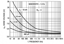
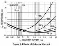
Oops, yes you're right! I posted Figure 2 of the MPSA18 datashseet, but Figure 3 might be closer to what member rayfutrell had in mind. Interestingly the "bottom out" point is about the same, approx 3.6 nv rt hz, leading to the same estimate of Rbb, 810 ohms. But 810 ohms seems awfully high.The figure you posted shows the noise voltage increasing with current rather than decreasing.
Attachments
This 2N5087 spec sheet gives a better example of what I am suggesting. See figure 12 of En vs Ic.
http://www.fairchildsemi.com/ds/MM/MMBT5087.pdf
I think the calculated MPSA18 Rbb is about right. I have some measured data I will try to find. I recall that the MPSA18 Rbb was not very low for a supposed low noise transistor.
http://www.fairchildsemi.com/ds/MM/MMBT5087.pdf
I think the calculated MPSA18 Rbb is about right. I have some measured data I will try to find. I recall that the MPSA18 Rbb was not very low for a supposed low noise transistor.
Here is a circuit that biases in input common base stage in a different way :
Patent US6069534 - Balance photo-receiver with complementary HBT common-base push pull pre ... - Google Patente
Here you can run the input transistors on more current then the base current of the second stage.
Patent US6069534 - Balance photo-receiver with complementary HBT common-base push pull pre ... - Google Patente
Here you can run the input transistors on more current then the base current of the second stage.
I would run at least 5mA, better 10mA in the input stage and use low Rbb transistors.
This is just part of the equation -- summing square of kernel, current and thermal noise. So is there such a big difference between 5mA and 10mA?
An externally hosted image should be here but it was not working when we last tested it.
I have a cartridge with 4 Ohm impedance so yes, i say 10mA makes a difference.
It may not be big but even in your graph you can see the difference at lower impedances.
Is that 1 or 2dB ?
Also when you make an open loop phono stage the higher Gm on higher idle can be an advantage.
It may not be big but even in your graph you can see the difference at lower impedances.
Is that 1 or 2dB ?
Also when you make an open loop phono stage the higher Gm on higher idle can be an advantage.
I have a cartridge with 4 Ohm impedance so yes, i say 10mA makes a difference.
It may not be big but even in your graph you can see the difference at lower impedances.
Is that 1 or 2dB ?
Also when you make an open loop phono stage the higher Gm on higher idle can be an advantage.
If you optimize Noise with respect to I(collector) -- this visual should demonstrate how much there is (or is not) gained:
An externally hosted image should be here but it was not working when we last tested it.
- Status
- This old topic is closed. If you want to reopen this topic, contact a moderator using the "Report Post" button.
- Home
- Source & Line
- Analogue Source
- Mr. Marsh's neat MC preamplifier