Hi,
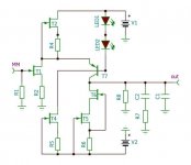
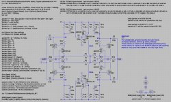
the circuit of #9763 is a complementary symmetrical Differential Amplifier.
The specialties here are the use of complementary feedback pairs (CFP or Sziklay) as gain devices.
Q1 and Q3 are the input transistors of a first differential amplifier.
Their emitters combined via emitter degeneration resistors R1 and R2 and supplied by a first constant current source Q7/8.
C6 denoises the CCS, imho it doesn't bootstrap it.
Output signals are developed over the collector resistors R11 and R13 and ac-coupled via C1 and C3 to the load resistors R26 and R18.
Q2 and Q4 and associated parts form a second Differential amplifier, complementary to the first.
That's output signals, developed over collector resistors R16 and R15, are ac-coupled via C2 and C4 also to the load resistors R26 and R18.
Q1, Q11 and R24 form a CFP or Sziklay pair with improved linearity (lower THD) and allowing for high bias current values (improving voltage noise).
Likewise applies to Q3,9/R12, Q2,12/R25 and Q4,10/R14.
See for comparison the prical schematic in #150 and the elaborated ciruits in #172 (single ended) and #152 (differential) in my 'Preamp-Buffers - simple idea' thread (Calvin buffer thread) for JFet-bipolar hybrid structures")
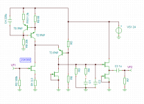
The circuit in #9766 forms a singleended folded cascoded.
Quite a bit different to the former
jauu
Calvin
the circuit of #9763 is a complementary symmetrical Differential Amplifier.
The specialties here are the use of complementary feedback pairs (CFP or Sziklay) as gain devices.
Q1 and Q3 are the input transistors of a first differential amplifier.
Their emitters combined via emitter degeneration resistors R1 and R2 and supplied by a first constant current source Q7/8.
C6 denoises the CCS, imho it doesn't bootstrap it.
Output signals are developed over the collector resistors R11 and R13 and ac-coupled via C1 and C3 to the load resistors R26 and R18.
Q2 and Q4 and associated parts form a second Differential amplifier, complementary to the first.
That's output signals, developed over collector resistors R16 and R15, are ac-coupled via C2 and C4 also to the load resistors R26 and R18.
Q1, Q11 and R24 form a CFP or Sziklay pair with improved linearity (lower THD) and allowing for high bias current values (improving voltage noise).
Likewise applies to Q3,9/R12, Q2,12/R25 and Q4,10/R14.
See for comparison the prical schematic in #150 and the elaborated ciruits in #172 (single ended) and #152 (differential) in my 'Preamp-Buffers - simple idea' thread (Calvin buffer thread) for JFet-bipolar hybrid structures
The circuit in #9766 forms a singleended folded cascoded.
Quite a bit different to the former
jauu
Calvin
Last edited:
Calvin, i published that circuit because of the low noise CCS.
It is the input stage of the Pandium we design at the Frickelfest Forum.
The Pandium is a " Digital " phono amp.
The Abraxas is used as a linear, balanced input for MC.
Then follows a second linear balanced stage with variable gain to optimise the dynamic range of the following A to D converter.
Without the Abraxas that second stage is the MM input.
After linear, balanced amplification the signal from the Cartridge goes into the balanced input stage of the AD converter. The RIAA compensation ( or others like Decca, EMI etc. ) is then done in DSP with software. The output is then a DA converter.
Salas, i have to search for the sim files. In praxis that circuit is very quiet and has very low distortion. It can be used in many configuarations, balanced and unbalanced at the input and the output.
Last edited:
I am a big fan of Szikley stages ( when they are stable ) and as you know i use your Calvin buffer with stunning results.
I have designed the Abraxas circuit before i first met you though.
Knowing the good results of the Abraxas i was immediate interested in the work you did on hybrids.
I have designed the Abraxas circuit before i first met you though.
Knowing the good results of the Abraxas i was immediate interested in the work you did on hybrids.
Yes, that cap of 220uF in the CCS is interesting. First we had put it to ground but putting it towards the PSU gave much better results.
For me that is a kind of bootstrap but anyway. We have seen many sides of discussion about certain names that describe certain circuits and it newer comes to a conclusion.
Hawksford Cascode, Current Feedback and so on.
I have no problem to give up the name Bootstrap for that circuit. Call it what you will.
For me it is more important that it works.
Last edited: