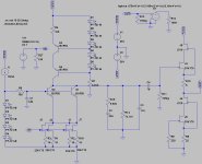
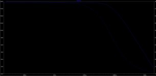
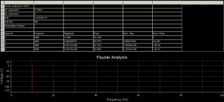
Ok, here is what my simulator spitted out. Gain is 57dB and good riaa compliance with increased shunting resistor from 130k to 142k. Typical nice SE harmonic distribution for 1Vrms out with H2 dominant. There was missing bias resistor for buffer, added that.
Sampler,
I tried to simulate that with LTSpice but it doesn't seem to work.
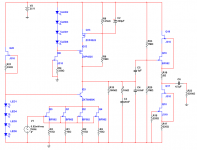
In attachment the circut I am simulating.
Do you see anything wrong with it?
Model for the Mos are taken from the manufacturer's website.
Attachments
I think R19 is not necessary.
You should get less gain with this circuit because the 2SK170 are less steep then the BF862
( less Gm ).
I am building the input gain cell at the moment in it´s most basic form, so lets see if it works.
Stafano, you should also raise R12 in value or the voltage over the CSS can break down.
It is better to make the CSS a little bit weaker in current supply compared to the input stage
then the other way around.
I am building the input gain cell at the moment in it´s most basic form, so lets see if it works.
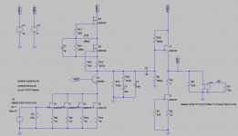
Good, let's see what a real world throws out. Meanwhile I have done some homework, that may apply hear if DN2540 ccs misbehaves. One solution would be mosfet gyrator, that would do some self biasing. Zetex makes nice HV mosfets with very low Coss, so we get a good improvements in BW and THD, as parasitic capacitances are main source of non linearities here. Spice tends to agree with me (see attached). Don't know about noise though, it's always uncertain with mosfets. It could be a surprise in both ways. I think this could be made all smd with mosfets and bjt in sot223 and jfets in sot23. I'm starting to like it
")
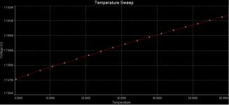
What JG said, try to step. R12 and plot Q1 collector voltage for ~18V op point.I tried to simulate that with LTSpice but it doesn't seem to work.
Attachments
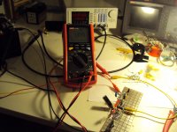
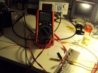
I build the input stage and there is too much thermal drift. I ballasted the output with 100kOhm and took a 25V supply ( two 12V lead batteries in series ).
The situation is that the BD139 goes into saturation when the voltage drifts down.
The voltage over the Fet´s is stable because the Leds minus Ube force that.
The situation is that the BD139 goes into saturation when the voltage drifts down.
The voltage over the Fet´s is stable because the Leds minus Ube force that.
Well, the depletion Mosfets are not the solution anyway. I may try my original BJT design.
When the thermal drift and the noise from the CCS is in check this may work.
Is it something you posted here on this thread?
I just checked out the thread: have you built the circuit simulated by sampler?
Have you measured the gain it it actually boosts out about 60dB?
Is just the DC drift a concern? Keeping in mind this is OL design, my practice is to eliminate the output capacitor, power the buffer, like MiiB also suggested, with dual supply and trim the offset down and close the servo around the buffer to correct DC drifting.
Would this work? I would be interested to get this model up on my simulator to check noise out.
For instance speaking of paradise, re-designing the circuit with BJTs and eliminating the bias el cap, simulator forecasts a whooppy 1.3uV/rtHz @1KHz.
Building it confirms exactly simulation and puts too much noise out which if in one hand sound is much better, the noise is something definitely unwanted.
Therefore after this test I became really concern about having a low noise phono as it is something I really like about the paradise topology.
Just a thought.
Post 7760 is the original design.
Concerns are low noise from the CCS and little thermal DC drift of the input stage.
I already know that a one stage RIAA is theoretical possible.
My tube RIAA comes close but has some gain in the output stage and that with only 8mA in the input. Here we have 50mA on tab so enormous gain in one stage is the attractive idea. So far i have only build a prototype of the input stage but my tube RIAA supports the theory.
I think it is not wise to take out the elcaps in the Paradise. Be careful with noise, that can at first listen sound very attractive because some unpleasant artifacts can be " analog dithered " away. We had a discussion with Salas here on this thread. If you want low noise without the elcaps redesign the Paradise for Fet input. That is simple.
This design can't be switchd to bjt's as you need the selfbiasing of the jfets..
I see the single-ended One shot design being possible too, but as I'am away, I can't get it into my simulator.
I don think the buffer need,s a servo. It's quite steady, low in drift, so weny you dail it in it stays there. Off course if you play with an unregulated supply's then a servo would be good.
Last edited:
Stefanoo is back, hello.
No, this is a Spiral Groove SG1. I am very happy with that deck.
Just saw your post! Thanks! Hello to you too!
This design can't be switchd to bjt's as you need the selfbiasing of the jfets..
I see the single-ended One shot design being possible too, but as I'am away, I can't get it into my simulator.
I don think the buffer need,s a servo. It's quite steady, low in drift, so weny you dail it in it stays there. Off course if you play with an unregulated supply's then a servo would be good.
it's about time to throw on the burner the one-shot design too (I will probably take that back to the masterpiece thread).
The goal for me would be to design an alternative using same custom V-Cap Cap 11nF and 32nF that work on Paradise as well.
Let's see!
Post 7760 is the original design.
Concerns are low noise from the CCS and little thermal DC drift of the input stage.
I already know that a one stage RIAA is theoretical possible.
My tube RIAA comes close but has some gain in the output stage and that with only 8mA in the input. Here we have 50mA on tab so enormous gain in one stage is the attractive idea. So far i have only build a prototype of the input stage but my tube RIAA supports the theory.
I think it is not wise to take out the elcaps in the Paradise. Be careful with noise, that can at first listen sound very attractive because some unpleasant artifacts can be " analog dithered " away. We had a discussion with Salas here on this thread. If you want low noise without the elcaps redesign the Paradise for Fet input. That is simple.
I will try to simulate your original desing from post #7760