Tanks Frans
so that is version (more or less) for Paradise .
I see that I need to reconsider the limits for the input / output voltages so not to need class A amplifier size sinks.
Maybe a LM317 to keep imput voltagge 6 V abowe wanted output voltagge wuld be a beter option
An LM317 will not help, this is the same work that is done by the first stage CVS and it just would create the need for 6Volts more on the input. In fact a shunt regulator is like a class A amplifier, it dissipates all power when idling.
Tanks to Joachim I have the 2 common mode cokes as spec
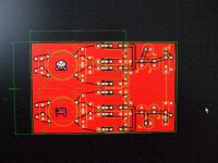
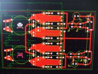
New board lay out ready for acid bath
Footprints for MKP4 up to 7 mm width and raster from 10 to 15 mm
Footprint for vertically mounted resistors (much tidier this way)
I have area on picture for the foot print sizes could you please double check
And let me know of any further changes as needed.
Just noticed missing cooper pour around output tracks that is now ok
Picture 1 The all thing
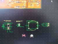
2 foot prints
3 for clarity no ground plane
PS I have sent couple of PM (Joachim your box is full again)
PSS tanks Joachim for the cokes arived earlier shuld be able to send boards by Monday
New board lay out ready for acid bath
Footprints for MKP4 up to 7 mm width and raster from 10 to 15 mm
Footprint for vertically mounted resistors (much tidier this way)
I have area on picture for the foot print sizes could you please double check
And let me know of any further changes as needed.
Just noticed missing cooper pour around output tracks that is now ok
Picture 1 The all thing
2 foot prints
3 for clarity no ground plane
PS I have sent couple of PM (Joachim your box is full again)
PSS tanks Joachim for the cokes arived earlier shuld be able to send boards by Monday
Attachments
Last edited:
Jose, the recording is:
Mercedes Sosa " Todavia Cantamos!".
The dog is at the beginning of : "Triptico Mocovi"
It is on "Tropical Music" from Marburg, Germany
That label made other awesome recordings
Joachim,
here it is on youtube:
Mercedes Sosa (1983) 04- Tríptico mocoví. - YouTube
At which time should I expect the dog on this track?
regards,
Hartmut
sounds like mp3 ate that dog for breakfast ;-))
sorry hartmut I had to say it....
MP3 will eat and digest an (smoked) Elephant even before breakfast.
http://www.youtube.com/watch?v=gXYfnWRp1Q0
The dog is there, even in this MP3 just before the big Pan Flute starts. It just does not sound "Waa Wuuuff!" like in my system but rather like "Ähk Ahh" or "Wah Wah" or even "Ah Ah", rather soft. Also the "space" around that bark is missing, it also has no focus. In my system you can locate the dog around 20m in the depth plane, ear level, slightly right off the middle.
Tanks to Joachim I have the 2 common mode cokes as spec
New board lay out ready for acid bath
Footprints for MKP4 up to 7 mm width and raster from 10 to 15 mm
Footprint for vertically mounted resistors (much tidier this way)
I have area on picture for the foot print sizes could you please double check
And let me know of any further changes as needed.
Just noticed missing cooper pour around output tracks that is now ok
Picture 1 The all thing
2 foot prints
3 for clarity no ground plane
PS I have sent couple of PM (Joachim your box is full again)
PSS tanks Joachim for the cokes arived earlier shuld be able to send boards by Monday
It looks great, I can see no problems.
Michael and i are working on a redesign of the Paradise to make it DIY prove.
Actually we are thinking that the buffer could cause oscillation so it will be subtituted by a much simpler well proven design that sounds at least as well. It is my floating cascode Fet buffer. Michael also has put all kinds of current mirrors thruw the paces and the design he came up with has higher output impedance, less distortion and is less critical in terms of Hfe matching. It is also less complex from component count. I already rebuild Heseners boards with the new mirrors and i think it sounds more dynamic. Michael also sugested to use BJT Arrays. That makes success even more easy.
Of cause Frans´s new PSU will be implented and the layout will hopefully have a working grounding scheme.
Would ATL consider the issiue of super secret hi current version.
I don't have the skill to modify that SCH
a variable +- 15 to 35 V at 1 A version would be realy outwordly
So here it is 5 to 35V up to 1Amp, maximum dissipation at IRFP924 35Watt (when Vout 35Volt @ max 1Amp), and at each of the power transistors 17Watt (when Vout = 5Volt @ max 1Amp).
Attachments
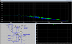
So here it is 5 to 35V up to 1Amp, maximum dissipation at IRFP924 35Watt (when Vout 35Volt @ max 1Amp), and at each of the power transistors 17Watt (when Vout = 5Volt @ max 1Amp).
Awesome graph
")
What are the fdw parts ?
Awesome graph
What are the fdw parts ?
That are LT413 variable shunts.
Look up TL413 and you find it. That was a typo i think.
another typo? TL431 I think