Here is the basic schematic of the preamp i am working on. It is a modified D.Self 2012.
I left out the tone control and raised the resistor values by 2. That worsens the S/N by 3dB but gives less distortion, especially in the treble. There are no electrolytics in the signal chain and no servo. S/N is still better then the original Self Precission preamp from 1996 or my version the JG-Self. I also chose different opamps and did some buffers that have to drive 1kOhm discrete. The differential opamp can be biased into class a. That is adjustable during listening and can also being switched off. There is a direct output in case you have a poweramp in japanese style with a volume control.
I left out the tone control and raised the resistor values by 2. That worsens the S/N by 3dB but gives less distortion, especially in the treble. There are no electrolytics in the signal chain and no servo. S/N is still better then the original Self Precission preamp from 1996 or my version the JG-Self. I also chose different opamps and did some buffers that have to drive 1kOhm discrete. The differential opamp can be biased into class a. That is adjustable during listening and can also being switched off. There is a direct output in case you have a poweramp in japanese style with a volume control.
Attachments
Looks cool, maybe to cool
For anything up to a few amperes you will not need a heat sink (especially not for the TO220 devices).
This is true for wire
This is true for wire
And TO220 diodes
") the device is going to be used at 160mA and for sure a pair of 1N4002's will be enough and these are rated 1A.
the device is going to be used at 160mA and for sure a pair of 1N4002's will be enough and these are rated 1A.And where would you mount the heat sink on a NUR460?
My point was that under the conditions set by the Paradise, it would be 'over kill' to add heat sinks to those diodes.
Thats correct, 160mA * 0.6V = 96mW, so we can rely on the "built-in" heatsink of the TO220 package. In my prereg, I use only one set of diodes so 200mW each, no heatsinking, and it works without problems.
I would not go above 1A though without heatsink.... it will improve lifetime
just my two cents...
I would not go above 1A though without heatsink.... it will improve lifetime
just my two cents...
Some more explanation about the JG-Self 2012. I use OPA1611 opamps that perform better when they are not loaded with less then 2kOhm so i doubled the resistor values in the feedback. The diffential opamp has a discrete buffer and can be driven into class A by the BJT current mirror. It can be from 1mA to 6mA and changed while listening. That can also being switched off. I use discrete buffers when 1kOhm is to drive. They have 8mA class A so they can swing 8V into 1kOhm. This is especially important in the output stage. When we use the direct output i can not imagine a load of less then 10kOhm, so the buffer never leaves class A. In the output stage there is gain behind the buffer and that relaxes the burden too. The drive requirements go down by the factor of the shunt feedback that is 3,3 / 1. The output stage uses the LME49713 current feedback opamp. It is very fast and low noise and can swing 100mA so no paralleling is necesarry. It also comes in a metal case that is supposed to sound better. There is a headphone ( 2 Ohm ) and a line output ( 10 Ohm ). Both very low impedance. I found that this improves slamm in the bass.
Hi Joachim / FdW / hesener
I am going to order same more capacitors for the pre regulator.
I was thinking Wima MKS4
What is your favorite type?
Same for resistors
2.2 Homs W ? type ? would wire wound be beter in this?
Wuld 20 mm Fuses holders be a worthy option at output
I am going to order same more capacitors for the pre regulator.
I was thinking Wima MKS4
What is your favorite type?
Same for resistors
2.2 Homs W ? type ? would wire wound be beter in this?
Wuld 20 mm Fuses holders be a worthy option at output
Hi Joachim / FdW / hesener
I am going to order same more capacitors for the pre regulator.
I was thinking Wima MKS4
What is your favorite type?
Same for resistors
2.2 Homs W ? type ? would wire wound be beter in this?
Wuld 20 mm Fuses holders be a worthy option at output
Vishay PR02 would be my resistor of choice
http://www.vishay.com/docs/28729/28729.pdf
MKP's is my capacitor of choice, Wima is great.
Ok had "quick" look at what is out there
Mouser stock the MKP4 range.
(I would like to stay with rule one for this project whic I understand is to use easily avvaliable parts)
They have 10 different capacitor listed from 7.5 to 22.5 pitch
I think we do not need the 2000 V rated ones
To stick with 250V (overkill)
Pick your flawor for 5% or 10%
foot prints are 10 and 15 mm.
I have no problems with those 2
For the resistors Joachim proposed type will fit nicely on a 15 mm spacing
FdW resistor require a 18 mm pitch unles wires are bended to a 15.
I will have to play about with the resistor position on the current board...
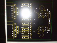
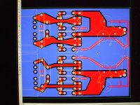
There you have it
(bit of tidy up to do but not much)
Same board caps foot print 10 and 15
Resistor foot print 15 and 18 mm
Straight pictures from monitor (take less to change a board around than to print and post new drawing.
Board blue HI light on ground (botom half need same cooper poor area... later
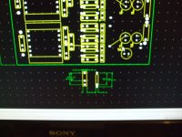
Silk screen
And silk screen close up for new foot prints
(bit of tidy up to do but not much)
Same board caps foot print 10 and 15
Resistor foot print 15 and 18 mm
Straight pictures from monitor (take less to change a board around than to print and post new drawing.
Board blue HI light on ground (botom half need same cooper poor area... later
Silk screen
And silk screen close up for new foot prints
Attachments
There you have it
(bit of tidy up to do but not much)
Same board caps foot print 10 and 15
Resistor foot print 15 and 18 mm
Straight pictures from monitor (take less to change a board around than to print and post new drawing.
Board blue HI light on ground (botom half need same cooper poor area... later
Silk screen
And silk screen close up for new foot prints
beautiful!
Metal films chosen by Frans are supposed to be less noisy then the metal oxide i use. At that low value of resistance it does not make a difference i think.
Even 63V is enough for the caps. I would prefer MKP4 though.
Also they (maybe) a little more stable, but you are right about the application context here, it will not differ.
Setting the resistors upright might an advantage, the proposed resistors are 75 K/W and getting a bit more air around them will help. So I do not mind the selected drilling spacing.
P.s. The board looks real nice!