Ricardo, there is another way to compensate the buffer that does not require to cut tracks and insert a resistor. Simply bypass the buffer from input bases to output after the 15 Ohm resistors,. That bootstrap reduces the current gain to zero at high frequencies but keeps the voltage gain that is aprox. 1x. A 15pF mica or COG should do. When you really want to optimize the impulse response of the buffer in the timedomain you have to isolate the buffer by not stuffing the RIAA and not connecting the outputs of the mirrors to the bases of the buffer. You than need a say 47kOhm resistor from bases buffer to ground to establish a DC current path and use the input of the buffer as input of your generator. Put in a 100kHz square at ca 1V and measure the square wave with a scope at the output. Adjust the bootstrap cap for minimum overshot of the square. Sometimes you need the input RC filter too or you have to insert a low value resistor in series with the bootstrap cap. In Praxis, with the RIAA in place the signal is shunted to ground anyway by the "treble" cap so i do not expect a major oszillation problem of the buffer. What can happen is that the PCB tracks from RIAA to input of the buffer, although short can produce a resonance with the input impedance of the buffer. That is damped of cause by the "bass" resistor and so it goes.....
Thank you... I like this one better.... Your previous solution might interfere with the riaa itself
")
To make the RC compensation work we need an additional reasisrtor from bases buffer to ground, i forgot that. That resistor is of cause parallel to the "bass" resistor in the RIAA so the RIAA resistor is to be raised in value so that the parallel combinations of the two resistors have the same value as the original.
There are other compensation methods possible inside the buffer but i need MiiB on that.
One possibility is the Ahuja compensation by Dr.Ahuja.
There are other compensation methods possible inside the buffer but i need MiiB on that.
One possibility is the Ahuja compensation by Dr.Ahuja.
This compensation method also improves PSSR by 70dB !IEEE Xplore - An improved frequency compensation technique for CMOS operational amplifiers
Attachments
Here is a discussion about Ahuja compensation with contributions from Putzeys, Gromer and Self :Ahuja-Compensation
This is what i call "forward compensation" and does not shunt the signal to ground plus other advantages.
See two circuit by Putzeys and Self.
My next post will show traditional Miller compensation.
This is what i call "forward compensation" and does not shunt the signal to ground plus other advantages.
See two circuit by Putzeys and Self.
My next post will show traditional Miller compensation.
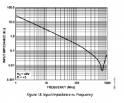
This is the problem with fast buffers. Here is the input impedance of a high speed opamp, so this is not the Pardise buffer but it is similar.
First you see that the buffer has a falling input impedance to higher frequencies. You can interpret that as an inductor. Then we have a null and then the input impedance goes up again by capacitive coupling from input to output. It would be best that from the null on the impedance would go smoothly down without rising again. That is quite hard to get because we are talking very high frequencies here. A better choice is to roll of the impedance much before that peak, say starting at 1Mhz so we have only a single pole with 6dB octave drop. That has also a good phase response because it is a first oder filter. This is what the bootstrap cap does but there is even a better solution. Stay tuned.
First you see that the buffer has a falling input impedance to higher frequencies. You can interpret that as an inductor. Then we have a null and then the input impedance goes up again by capacitive coupling from input to output. It would be best that from the null on the impedance would go smoothly down without rising again. That is quite hard to get because we are talking very high frequencies here. A better choice is to roll of the impedance much before that peak, say starting at 1Mhz so we have only a single pole with 6dB octave drop. That has also a good phase response because it is a first oder filter. This is what the bootstrap cap does but there is even a better solution. Stay tuned.
Attachments
In the Riaa.. with out the neuman resistor, you have a one pole drop all the way up....Should not give any global problems...if you use the neuman resistor a smaal cap across that should give sufficient roll off....when i get to my comp again I'll try to give an idea of the value so the roll off is placed at app 500 KHz
Last edited:
Yes, that is what i said, the "treble" RIAA cap shunts the signal down to ground.
I was talking about the buffer in isolation.
I have e-mail contact with Hesener and the oszillation problem may come from something else. He works on a solution that has to do with grounding.
The group buy PCBs may have another grounding scheme with a full ground plane except the PSU. Good, that we wait a bit until we release an official version everybody can buy.
It is really a minor issue that should not be beaten to death.
How the Paradise really works, from our ATL lab in the US :Turbo Encabulator - YouTube
Almost done.
Riaa caps in place, 130k also... leaving the 15k for tomorrow. ( must match them and am quite tyred )
I am wondering about C105 / 205 10u caps... using computer caps there (very low ESR) hope I will not listen to the infamous "Wistle"....
These caps are placed under the heatsink and I also discovered that it is very difficult to remove any small part once it has been soldered.. the tiny holes get filled with solder that can not be easily removed.....