Thanksand yes I think so
Here a version with the filter, snubber resistors and LED's. The current has now been set to 150mA ( 105mA for the amplifier, 45mA to warm the planet).
When finished it will signal HAPPY HOLYDAYS

Seems like it get's better with 22 ohm degenration....but again worse with 10ohm, so 22ohm could be a sweet-spot at least for simulation...distortion looks good...
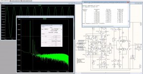
I have also made distortion analysis at 10KHz, where the gain is 46 dB, and here the current RIAA really shows what's it's all about, Distortion drops quite a bit. This is the ultimate strength of this circuit, Lowering distortion as frequency increases and no feedback. Only type of circuits i know off that is capable of this...)
I have also made distortion analysis at 10KHz, where the gain is 46 dB, and here the current RIAA really shows what's it's all about, Distortion drops quite a bit. This is the ultimate strength of this circuit, Lowering distortion as frequency increases and no feedback. Only type of circuits i know off that is capable of this...
)Attachments
Thanks
Here a version with the filter, snubber resistors and LED's. The current has now been set to 150mA ( 105mA for the amplifier, 45mA to warm the planet).
Sorry: Transistor Q1 has E and C exchanged (it is upside down). Attached is the corrected schema.
Attachments
I'll go over the schematics Once again to make sure that currents and derating is ok...don't want anyone to make layouts with the result at components burn as they dissipate too much, now we have 15 mA through the output devices, could be a little too much, what do you think..??
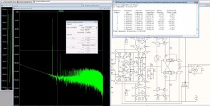
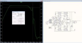
This is how it looks distortion-vise at 100 Hz, where the gain is a whooping 80dB
and the signal out is +-3V (will never happen)
max voltage-swing before visual clipping is app +-8V
This is how it looks distortion-vise at 100 Hz, where the gain is a whooping 80dB
and the signal out is +-3V (will never happen)
max voltage-swing before visual clipping is app +-8V
Attachments
That looks very good and with even less noise then the 50 Ohm degeneration. I am very pleased. I think we are more or less there. Who will do the layout ?
Hi , standing by for doing this but if Bksabath wants to give it a try, fine by me. I am assuming that we will layout a mono board, with the power supply and preamp for one channel on it.
I may however not be able to proceed at this lightning speed this group of highly skilled people is advancing... this is purely amazing!!!
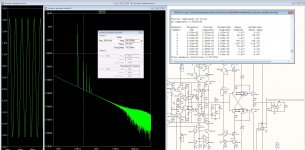
I have some issues on the BW plot, as there is a gain-peak/resonance at 44 MHz, I think that PCB trace-capacitance/resistance will deal with this, but more skilled people than I must chip in here, could be we need some compensation....Only thing is I'am clueless where to place it..
Attachments
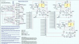
The only non-mirrored item in there is J4 at the cost of 4 transistors (6 cents) it could be replaced by this nice mirrored ccs Do not worry too much about the 44Mhz, I think also it will go/disappear on the board, and if not it will be easy to hunt down (I think).
Do not worry too much about the 44Mhz, I think also it will go/disappear on the board, and if not it will be easy to hunt down (I think).Attachments
No problem with an adjustable RIAA....Just make different deemphasis networks and switch them in...
The buffer i one half of the peaking, I believe in a practical circuit there will be none..
I thought about putting in the same CCS as we use in the front end
The buffer i one half of the peaking, I believe in a practical circuit there will be none..
I thought about putting in the same CCS as we use in the front end
Attachments
Yes, Rüdiger. I would do an RC filter before the buffer. The peak comes from the buffer i suppose but is is very high up so input impedance must be quite linear. First it gets inductive and then capacitive. Maybe we should limit at 1 to 2 MHz, then we have a nice Q 0,5 rolloff with very little phase change.
Something like 220Ohm in series with the input of the buffer and 150pF to ground.
We could make the RIAA adjustable, i really do not know if that is on the wish list too.
Hesener, you have my blessing so please communicate with Bksabth about this. Maybe you can work together, i really do not know. Yes, i would do the circuit as a mono board with regulator on board. I would then put the transformers, the common mode coils and the bridges plus 2200uF including small decoupling foil caps on a separate board and in a separate case. Frans, i have to look up where you would like to put in the new mirror.
So it is an infinite mirror, we can that Spiegel im Spiegel in Germany (;
Michael, running the output trannis in 15mA at 24V gives a dissipation of 0,36W. That is approximate half of what the transistors can stand. this is still ok for me. We could also use two plus two i parallel with separate emitter resistors with double value. That is more linear and gives half dissipation.
Can we consider the option to use a higher current in the psu shunts ?
IMO irf9610 starts to sing between 180 and 200mA.... I even noticed some improvements using those at 300mA. I know it is a big waste of heat but substatntial sonic gains can be achieved that way
No problem
but not needed, overdone maybe (and I like that) Ok, so what EQs do we want ? One that is important in Germany is the DIN norm with 50usec instead of 75usec. The cutting lathes here had a switch between those too and some records have being cut with 50usec here in the old days. Then we need EMi and Decca. What else ? The infamous Neumann peak at 2.2usec can be introduced with a resistor in series with the 75usec cap if somebody believes in that.
Frans, i have to look up where you would like to put in the new mirror.
I was not totally serious about that, I just thought to sell another 4 transistors, it won’t make any difference
that's why it had the smiley Can we consider the option to use a higher current in the psu shunts ?
IMO irf9610 starts to sing between 180 and 200mA.... I even noticed some improvements using those at 300mA. I know it is a big waste of heat but substatntial sonic gains can be achieved that way
Anyway, lower R5/R6 to 6.8 or even 5.6 and the current starts flowing no need to change anything else. Be sure to use a bigger transformer and double the buffer elco's (if you are busy at that). The current that will flow is 1.25Volts / Rset = Iccs. And (Iccs - 105mA) * 37Volt = Wwarm-the-world.
Last edited:
If i would have the final saying then i would prefer to get the job done just right and not over engineer it. Too much heat is not what i want. The circuit itself has superb suppression of PSU anyway. Cascoded mirrors, cascodes with mirrored and shunted bias everywhere.
This is not a simple single ended phono where the break through of the PSU is clearly audible.
This is not a simple single ended phono where the break through of the PSU is clearly audible.