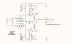
I have some difficulty getting the Simulation going....Circuit as shown has a gain of app 30 db....I must be missing something...Or the simulator is playing games with me...!!
Currents seems Ok with app 22 mA running through all branches and cascode voltage is app 8 V..Hmm....(tror der er en nisse på spil)..!!
michael
Currents seems Ok with app 22 mA running through all branches and cascode voltage is app 8 V..Hmm....(tror der er en nisse på spil)..!!
michael
Attachments
Rüdiger, yes, this phono is made without Fets. First because P-Channels are nearly unobtainable and second because of cost. The input stage can of cause be setup with Fets but not this time. I played around with other biasing methods for the cascodes. I have to search this thread because i have published my solution somewhere here. I also build your version with the little shunts but did not get it working. A friend of mine even made a PCB that i tried to debug without success. If you like i can send you the stuffed PCB´s. Maybe i did something wrong. I have of cause also tried the Salas but i am often running into oszillation problem. The Salas has less then 5mOhm output impedance and does not allow a low ESR cap at the output. My solution is absolutely stable and it can be enhanced with a low ESR cap at the output. The output impedance of my circuit ( actually it is not mine but a mixture of Holgers and Werners ) is around 40mOhm and can be lowered in the treble with a low ESR cap. The pass transistor at the output could be setup as a Szikley for more regulation but i did not try this. Actually i would prefer if we do not use the Salas, i really would like something simpler and different. I know that it is the de facto standard and has an impeccable reputation.
MiiB, yes the cascodes run on too little voltage. Raise that to 14,5V please. That are around 8 green Leds or something different. C2, C3 are 100m on your schematic. I think 10m is enough. You load the output with 1kOhm and get a gain of 30db instead of 40dB.
That can be because i interpolated the values from the Starless. This circuit may have a lower output impedance. We can raise the values of R7, R8, R10, R11 or use higher resistance values in the RIAA. We can also do another layer of mirrors on top.
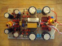

why did you paint the transistors in red ?
After extended Listening sessions we have found out that painting the top of the transistors with this nail laquer (PRITI NYC MINI Nagellack - keepsake rose - Zalando.de) gives a better resolution in the higer mids.
Maybe caused by the additionel damping.

Sam
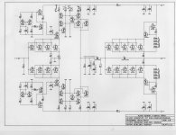
Sam, am i allowed to post the circuit diagram here ?
Yes, of course. It is your design. Klaus did the PCB design, I was only the sponsor of this J-fet grave.
")
I will ask Klaus weather he will do a layout for the paradise lost.
Sam
Hi Sam,
pleased to meet you here again.
pleased to meet you here again.
Just can't imagine how many listening test you had to absolve 'til you picked the right laquer.....After extended Listening sessions we have found out that painting the top of the transistors with this nail laquer (PRITI NYC MINI Nagellack - keepsake rose - Zalando.de) gives a better resolution in the higer mids.
That was state of the art one year ago, funny. That was at a time where i had illusions about offset in transimpedance stages. This thing needs a servo but i could not even make the bias work in the input stage so i stopped there. Benedetto, i can not find schematics in the link you send but i have heard about the circuits of cause. Can you find the schematics
?
?
Stolen ??
What? Who did that? If you find out who did it, than let me know
I'm sorry to hear this Joachim
You better buy a tablet and keep it with you all the time.
atb,
Audiofanatic
So here it is. I had to scan it because my computer was stolen in Munich at the High End Show.
What? Who did that? If you find out who did it, than let me know
I'm sorry to hear this Joachim
You better buy a tablet and keep it with you all the time.
atb,
Audiofanatic
It was in a youth hostal. I wanted to safe some money and took primitive accomodation. I had put my IBook in an unprotected baggage room. When i came back from the show the leather bag was still there but nothing inside. Why did those ******** not even leave the hard drive ?
20GBite of hard data. I do not even speak about the measurement and simulation software. I needed weeks to basically setup again. I have a fine Macbook Pro now but i swear that my IBook was the next day in Poland giving maybe 100,-€ on the black market.
It´s pathetic, those pricks really suffer a bad life.