Sure Ulf. It does not come much simpler then that. Still the performance of the FF2011 is very good. You can also use double Opamps per channel. The good thing with the ELV was that you also got a case, the Jacks and the PSU. Opamps of the new generation like LME49710 or OPA1641 are now so good that even a new generation Audio Precission can not do them justice without using some tricks to boost the distortion.
Yes, i published one. It was a Diamond Buffer with an inverted Opamp plus an input buffer.
Quite complicated. I would not do it this way again.
Over at Head HiFi i found a simple amp i like. I will post it here. It should be a bit modified with a stronger output stage. There is a thread on Diyaudio about a very high quality headamp. That should be as good as it gets. I will post that circuit too.
Here is the simple circuit. I would use stronger output transistors on a decent cooling profile. You can use 2SA1381 / 2SC3503 video transistors. The emitter resistors should be reduced until at least 50mA idle current flows.Something like 3.3 - 4.7 Ohm when you use a green Led. That gives around 80mW class A. If you can not find the video trannies you can use BD139 / 140 as well. Do not be afraid of the NE5534. It is still used today for example in the Violectric Headamps and in Accuphase CD players.
Attachments
Hi JG,
so i´m going to try the first (your recommended) circuit just for two
reasons...i have most parts at hand and my sources are unbalanced.
But just some questions:
QTLP690C is the green LED you were writing about?
rload is the imp of the Headphones i bet and when doing your changes
the circuit will be driving my Headphones, right?
Greetings ulf
Where are the P channels Sam ?
Yes, Ulf, with modification it will drive your 32 Ohm quite nice. Tell me how it sounds.
The Led i would use is a green 2mA. That gives around 1.8V when you drive it with more then 1mA. The current through the Led can be steered with the resistor in series with the Fet. The lower you make that resistor, the more current flows into the Led. You could use 10mA Leds too but then you need a bit more current to ignite it. The green Led will give a little more then 0.2V into the emitter resistors. So 3.3 Ohm emitter resistors give 0.2 / 3.3 = 60mA. Is that enough to understand the circuit, Ulf ?
Last edited:

Where are the P channels Sam ?
Fort Knox?
Speculators?
I don't know.
We have to talk about the Schlotzauer Buffer during FF
With kind regards
Sam
Ulf, i would take out the 5kOhm in series with the input and raise the 10kOhm from input to ground to 47KOhm. You may have tried to avoid common mode distortion but source resistance is a moving target anyway because you use a pot. The PSU on the drawing seems to be made for mobile purpose and has an "artificial" ground. I would use a simple conventional LM317 / 337 design instead with a transformer that has two secondaries. You can raise the voltage a bit if you like. You can filter the NE5534 Pin 4 and 7 with 22 Ohm in series and 100uF to ground and 0.1uF from Pin 4 to Pin 7. The output stage can be filtered with 5 to 10 Ohm and 2200uF like wise . You can put 2mA into the Led. I use 1mA only with noise sensitive phonostages and here noise from the Led is not critical. Other wise the drawing looks fine. Good luck.
Sam, i have build the symmetric Schlotzaur. I bring it to FF2011. I could not make it unity gain stable. It is simply too fast. Resonant frequency is 180MHz ! I made a kind of line stage with gain of 6dB and that works just fine.
Sam, i have build the symmetric Schlotzaur. I bring it to FF2011. I could not make it unity gain stable. It is simply too fast. Resonant frequency is 180MHz ! I made a kind of line stage with gain of 6dB and that works just fine.
Here is the classical Knightbridge 2mA green, from Schuro. You see that the curve starts exponentially and at 5mA it goes into a steep more or less straight line. So try 5mA, a bit more then i would use in a phono but as i said, noise is non issue here.
Attachments
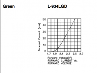
You see at 5mA the Led drops 2V, so i would start with 4.7 Ohm emitter resistors and then crank it until the output trannies on the cooling profile do not get hotter then 60° Celsius.
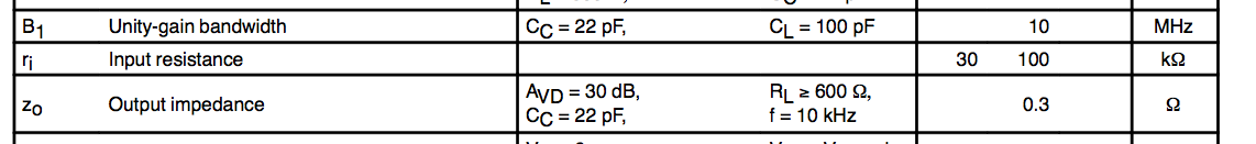
See the input impedance of the NE5534. It is 30kOhm minimum.
See the input impedance of the NE5534. It is 30kOhm minimum.