I have a motor question. While using a Portescap 7.5 degree, 24v stepper motor, running it at 81 Hz for 45 RPMs, makes it get very hot. Is it now running outside specs?
Try what I did . Take a speed controllable drill and rotate as best you can to the desired speed ( I used a spectrum analyzer to check Hz ) . Add a load of lets say 1 watt per phase at the suspected output of 14 V rms ( 200 R 1W ) . See what you get on both phases . I suspect that is the maximum voltage when used as a synchronous motor . As a rule of thumb 1/2 DC will be about right .
If you have the inductance of the motor go back to the stepper motor calculator I gave previously in a link . I suspect the ideal stepper rotational max is also very good at AC .
From my tests I would expect 8 to 10 V rms to work well with your motor . 24 V rms AC is about 34 V DC equivalent if a stepper , that would get hot .
A big Crouzet 11W synchronous as I show stripped down gets up to 60 C ( 140 F ? ) at full voltage . Some transformers are rated up to 130 C , a motor is a rotating transformer mostly . The big question then is vibration . the lower voltage will help both vibration and heat .
I hope soon to try a 1.8 stepper . I want 78 RPM . In fact I want 80 for an industrial application .
http://www.daycounter.com/Calculators/Stepper-Motor-Calculator.phtml
Last edited:
Hello.
My first post here, and I am already rambling...terribly sorry I posted this in the wrong thread, its not a DIY turntable I have....
I have a Micro Seiki BL-77 turntable, and with no skills as a DIY guy I attempt to understand this thing.
Parts are not easy to come by, I need a dust cover, the finger lift on the headshell is broken and the headshells are impossible to find, and I am looking at the transformer and motor to if things can be improved upon. I will have to buy another BL-77 in order to get parts I think.
Anyway, the motor in this thing is called Matsushita FG Servo Dc 12 volt MHX-5F2R VM but I cannot find any info on this motor. What I find is this, it looks identical, except the the original cannot be easily opened and doesnt have that screw on the side to pull out a pcb.
Matsushita DC Motor 12 V 6000 RPM 39 mm Diameter 12 V Motor Low Current | eBay
From the turntable to the motor there are five cables, amongst them two yellow, and on the e-bay motor there are four terminals, I am just assuming the two yellow cables go together, but I am not sure.
Thought I should try the motor, but I dont dare since I am not convinced where the cables go.
I have a bit of transformer noise, the table is specified to 220volts, we have 230 here but I measure up to 239 at times. I tried a dc filter, by LCAudio, but it didnt help really.
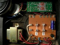
Thinking about getting an enclosure and mount a new toroid transformer, and the power supply board from the turntable in this new enclosure. The power supply board is shown on the picture here with the fuses. Still have to measure the original transformers output voltage before I can get a new one, but I assume its 12 volts since the motor is 12 volts.
Anyone knows if these old DC motors from Micro Seiki is still available, under another name maybe?
My first post here, and I am already rambling...terribly sorry I posted this in the wrong thread, its not a DIY turntable I have....
I have a Micro Seiki BL-77 turntable, and with no skills as a DIY guy I attempt to understand this thing.
Parts are not easy to come by, I need a dust cover, the finger lift on the headshell is broken and the headshells are impossible to find, and I am looking at the transformer and motor to if things can be improved upon. I will have to buy another BL-77 in order to get parts I think.
Anyway, the motor in this thing is called Matsushita FG Servo Dc 12 volt MHX-5F2R VM but I cannot find any info on this motor. What I find is this, it looks identical, except the the original cannot be easily opened and doesnt have that screw on the side to pull out a pcb.
Matsushita DC Motor 12 V 6000 RPM 39 mm Diameter 12 V Motor Low Current | eBay
From the turntable to the motor there are five cables, amongst them two yellow, and on the e-bay motor there are four terminals, I am just assuming the two yellow cables go together, but I am not sure.
Thought I should try the motor, but I dont dare since I am not convinced where the cables go.
I have a bit of transformer noise, the table is specified to 220volts, we have 230 here but I measure up to 239 at times. I tried a dc filter, by LCAudio, but it didnt help really.
Thinking about getting an enclosure and mount a new toroid transformer, and the power supply board from the turntable in this new enclosure. The power supply board is shown on the picture here with the fuses. Still have to measure the original transformers output voltage before I can get a new one, but I assume its 12 volts since the motor is 12 volts.
Anyone knows if these old DC motors from Micro Seiki is still available, under another name maybe?
Attachments
Last edited:
Try what I did . Take a speed controllable drill and rotate as best you can to the desired speed ( I used a spectrum analyzer to check Hz ) . Add a load of lets say 1 watt per phase at the suspected output of 14 V rms ( 200 R 1W ) . See what you get on both phases . I suspect that is the maximum voltage when used as a synchronous motor . As a rule of thumb 1/2 DC will be about right .
If you have the inductance of the motor go back to the stepper motor calculator I gave previously in a link . I suspect the ideal stepper rotational max is also very good at AC .
From my tests I would expect 8 to 10 V rms to work well with your motor . 24 V rms AC is about 34 V DC equivalent if a stepper , that would get hot .
A big Crouzet 11W synchronous as I show stripped down gets up to 60 C ( 140 F ? ) at full voltage . Some transformers are rated up to 130 C , a motor is a rotating transformer mostly . The big question then is vibration . the lower voltage will help both vibration and heat .
I hope soon to try a 1.8 stepper . I want 78 RPM . In fact I want 80 for an industrial application .
Stepper Motor Calculator
Nigel, Please suggest a value for the phase shift capacitor with this Portescap stepper motor being used as a synchronous AC motor 60Hz.
Thanks in advance,
BillG
Hi Bill .
I have just been working with the Linn LP12 for the first time in years . I must say the cheaper motor here seems a better motor if it can be slightly tamed . One massive advantage is that the voltage is low . That means safe to play with and cheap parts . On reflection a much lower voltage is worth trying . The LP12 motor is so puny yet works OK . The torque and vibration can he assessed by ear . You might only need 4 V . This little motor is pretty good if criticizing the typical motor . As a rough guide when the voltage is the same on both phases it is in the right ball park . Start with 10 uF and add some . If you buy some non ( bi ) polar caps these will be fine to get an idea . Perhaps buy a big value film cap later . To be honest the 50 V rated Panasonic's should last for years at this low current .
Here is an example . A few lower values also . You might need 18 uF ( could be a bit more ) . Start with 4 V rms so as to be able to gauge vibration .
ECEA1HN100U - PANASONIC - CAP, ALU ELECT, 10UF, 50V, CAN | Farnell UK
Sorry I did not answer this before . I suspect it didn't arrive in my in box ? I feel there is one very big error in what he says . RC oscillators are in no way inferior to typical crystal oscillators . The temperature coefficient of a NPO ( COG ) capacitor is 30 ppm . A crystal also . The resistors commonly used often compliment the NPO capacitors and can outclass a crystal . Thus surprising stability and accuracy is arrived at . Adjusted using a strobe needs no £500 frequency meter . A Wien Bridge RC oscillator needs no other filtering in a turntable application . A crystal needs plenty . Also some harmless assumptions he makes are of no importance one way or the other . What matters is phase , voltage and an attempt at reasonable waveform shape . If you want to optimize build a 100 F ( 40 C ) oven around the oscillator . That temperature is unlikely to be exceeded by room temperature . 20 to 25 C suits pickups best . If you have valve amps check this ( or any hot amp ) . 100 F / 40C is not unknown local to the valves . Your pickup will sound less than it's best . Japaneses PU's sometimes were specified 25 C for tropical markets . People in other countries were disappointed with their bargain imports if so , 20 C being more typical here .
Hi Bill .
I have just been working with the Linn LP12 for the first time in years . I must say the cheaper motor here seems a better motor if it can be slightly tamed . One massive advantage is that the voltage is low . That means safe to play with and cheap parts . On reflection a much lower voltage is worth trying . The LP12 motor is so puny yet works OK . The torque and vibration can he assessed by ear . You might only need 4 V . This little motor is pretty good if criticizing the typical motor . As a rough guide when the voltage is the same on both phases it is in the right ball park . Start with 10 uF and add some . If you buy some non ( bi ) polar caps these will be fine to get an idea . Perhaps buy a big value film cap later . To be honest the 50 V rated Panasonic's should last for years at this low current .
Here is an example . A few lower values also . You might need 18 uF ( could be a bit more ) . Start with 4 V rms so as to be able to gauge vibration .
ECEA1HN100U - PANASONIC - CAP, ALU ELECT, 10UF, 50V, CAN | Farnell UK
Nigel,
Here is the motor I've ordered, 2 of them. Thanks for your suggestions. Looks like I may get away with an old 6.3VAC filament transformer.
24V STEPPER MOTOR
Portescap #S42L048S02-M5. 24V, 5 Ohm, 7.5 Degree per step. 42mm diameter x 22mm. Two mounting holes on 51mm centers. Four 3" leads. Shaft - 3mm diameter x 11mm long. 16 tooth, 9.75mm diameter ...
Read more
CAT# SMT- At AllElectronics. Should be in next week
$2.50 each
Do you have any idea why a 117 VAC synchronous 300rpm motor from an old BIC TT won't start? On turn on it buzzes but no start running. Give it a manual spin and it runs right on speed and very quiet. Ive tried belt tension and slippage adjustments to no avail. If it would start by itself I could it and be very pleased.
Motor stops rotating
Hi Everyone,
I measured the coils on a motor and it reads 153 ohms. Both coils the same.
Does that equate to around to 1.75 to 2 watts full output on the amp providing the 60hz signal?
The amp rating is 50w to into 8 ohms. Its a T-amp.
Reason for the question is the motor doesn't start unless the platter is hand spun to speed.
The input to the amp has to be full input signal and full output on the amp.
The motor vibrates, but smoothes out if input level is cut back. Problem is at any given point, the motor will stop rotating.
Would a more powerful amp help or is the problem elsewhere?
Thanks
Vince
Last edited:
Nigel,
Here is the motor I've ordered, 2 of them. Thanks for your suggestions. Looks like I may get away with an old 6.3VAC filament transformer.
24V STEPPER MOTOR
Portescap #S42L048S02-M5. 24V, 5 Ohm, 7.5 Degree per step. 42mm diameter x 22mm. Two mounting holes on 51mm centers. Four 3" leads. Shaft - 3mm diameter x 11mm long. 16 tooth, 9.75mm diameter ...
Read more
CAT# SMT- At AllElectronics. Should be in next week
$2.50 each
Do you have any idea why a 117 VAC synchronous 300rpm motor from an old BIC TT won't start? On turn on it buzzes but no start running. Give it a manual spin and it runs right on speed and very quiet. Ive tried belt tension and slippage adjustments to no avail. If it would start by itself I could it and be very pleased.
Last question first . Usually if both coils read about the same all is OK ( meter ohms range ) . If so the capacitor is likely to be faulty . A magnet could loose strength . Don't think I ever saw that .
The motor I became confused with is a similar 12 V stepper . It seems to need about 4 RMS . We might infer a 24 V stepper will need about 8 V rms . I suspect a filament transformer lightly loaded will be not too far from what it needs ( 7 V rms ?? ) . 50 V caps will be fine .
Last edited:
Hi Everyone,
I measured the coils on a motor and it reads 153 ohms. Both coils the same.
Does that equate to around to 1.75 to 2 watts full output on the amp providing the 60hz signal?
The amp rating is 50w to into 8 ohms. Its a T-amp.
Reason for the question is the motor doesn't start unless the platter is hand spun to speed.
The input to the amp has to be full input signal and full output on the amp.
The motor vibrates, but smoothes out if input level is cut back. Problem is at any given point, the motor will stop rotating.
Would a more powerful amp help or is the problem elsewhere?
Thanks
Vince
It might be worth trying a transformer solution to establish what you need . Next step is use a T amp and phase shift capacitor to go to a supposedly superior solution ( not always , Naim Armageddon is transformer ) . Next move to phase shifted bi amp solution if you feel it would interest you . I suspect a well chosen capacitor is fine . The motor wattage is hard to say . The 153 R is in series with the coil inductance , by Pythagoras the impedance Z is the true load . My guess is it will be half what the resistance suggests . These motors seldom need more than 2 watts total . We should say VA . It serves well to say watts when this small . I suspect the T amp is objecting to the motor , a scope would confirm that . 153 R suggests low voltage . It is just possible an additional resistor might help ( 100 R ? ) . If you have a 12 + 12 V transformer that might tell you something . Try both 12 and 24 V . Be quick to turn off if beyond hand hold hot . I have just measured a Linn motor and another stepper . Linn 115 V type 4500 ohms . Astrosyn MY355 liking 4 to 6 V rms 24 ohms per winding . The coil resistance changes dramatically with voltage . Roughly the Astrosyn would be 24 x 4 R ( 100 R approx ) if double voltage .
The transformer test will say if you need a more powerful amp . 25 V rms suggests 100 watts if 8 ohms . My reverse engineered test suggests a transformer to be better than is said . You might try a 115 to 250 V transformer if you have one on the T amp . It would give a 1 : 2 step up . At such high resistance it should be OK . Be certain you don't get too high a voltage .
Nigel
I tried what I had on hand which is a 65w chip amp or gain clone.
I found that it was more apt to start spinning from a cold start, without hand spinning.
Left it running for around 5+ hours and it did not shut off. A good sign.
Still have to cut back the gain to reduce motor vibration, but this time the motor did not stop running.
With the amp/60hz mp3 file, I'm not using a cap. The sine waves are off set by 90 degrees.
Created on Audacity audio software.
Seems it needs very near it's stated DC voltage to work . 23 Vrms is 66 W 8 R . That says in fact hitting peaks of 32 V if using near full output . Slightly surprising . I suspect 12 V rms or less . Perhaps the T amp didn't like the motor ? Surprising as an inductor should be OK .
You could build a simple NE555 one shot circuit ( I uF and 4M7 gives about 5 seconds ) . A relay can change the gain . It will reset almost instantly if changing speed . I doubt you can catch it out .
The oscillator looks interesting .
You could build a simple NE555 one shot circuit ( I uF and 4M7 gives about 5 seconds ) . A relay can change the gain . It will reset almost instantly if changing speed . I doubt you can catch it out .
The oscillator looks interesting .
I have just looked at the Portescap 24 V motor . It has a 5 ohms winding which seems unusually low . The one I tested below is 24 R and 40 mH . The one of vdi is 153 R .
2 Phase Bipolar Stepper Motor 12v | Rapid Online
Using Pythagoras for the Rapid Electronics motor . If 60 Hz . Xl = ( 2Pi .60.40 )/1000 = 15 Z = / ( Xl ^ + R^ ) = / ( 801) = 28.3 R . In the case of the 24 R 12 V motor from Rapid the resistance is almost the whole story . If so the amp will be happy . If 5 R I would infer the inductance contribution is is minimal ( 6 R ? ) . Please correct the maths if wrong . Also if 5 R expect the capacitance required to be high to phase shift ( > 100 uF perhaps ) . All may not be a problem as a low voltage may work very well .
Last edited:
I did a bit of thinking about this . Even if the impedance Z is only 28.3 R the phase angle is considerable . 24 against 15 is -tan 0.625 or 32 degrees ( 12 V motor at 60 Hz ) . At 81 Hz 20.36 and 24 . -tan ( 20.36/24 ) = 40.3 degrees . That seems to me within an OK range . My experiments say slightly different . It could be my voltage wasn't high enough . What might be true is the heat will increase as the resistance is always resistance and the higher voltage to offset the inductance is still be passing through the resistive component .
here u are
http://www.diyaudio.com/forums/analogue-source/249108-custom-tt-project-complete.html
stuartarm: 1/2" thickness increase for a solid platter is a huge amount of mass being added. I didn't see the underside of the platter, but am assuming it is a solid disk of material. If not machined out, then a lot of energy is wasted and contributes little to the flywheel effect vs energy applied.There are a couple of ways to get to the same result. Multiple motors vs. massive platter is one. The key is to conserve momentum.
Feet have been designed in so many iterations that somewhere feet must exist. If wanting to do something strictly custom because you can, that's OK. However unless you have some fairly sophisticated measuring equipment it is unlikely you will improve on existing designs.
I look forward to seeing the end result.
http://www.diyaudio.com/forums/analogue-source/249108-custom-tt-project-complete.html
Stunning!
Not to my "taste" (design-wize), but absolutely stunning. The level of fit and finish and your attention to detail is top notch and I doubt could be improved upon. I had assumed you were doing all of the machining or paying for all custom machining and had not realized you were purchasing parts, but the end result must be worth the effort.
I know nothing about the tonearm, but had a F9E for some time and loved it. I am sure you are absolutely proud (as you should be) and must be enjoying the listening experience. Kudos to you!
Aside from the tonearm, cartridge, controller and record weight the rest of the TT was designed by me and custom made by three different companies.
- Status
- This old topic is closed. If you want to reopen this topic, contact a moderator using the "Report Post" button.
- Home
- Source & Line
- Analogue Source
- motor and circuit for diy turntable project