try moving output node somewhere else
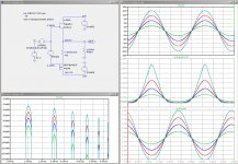
didn't tried these tricks with PapaSit , but SUFI-SIT sim (#443) is best arangement I could get , with this brain
I did sims of DEFiSIT , to grasp as much I can , but didn't tried to make it better than it is
How does the actual sound compare at the different positions?
Actually it is CLASS-A, PUSH-PUSH!
just realized that there is new class of amplifier output stage , invented by Pa
∀ Class
How does the actual sound compare at the different positions?
why should I try something which is so obviously worse in simulations ?
worse means - pretty much same THD spectra , but worse in level
as you pretty well know , one must have specific level of trust in simulations , not just based on general verity of simulations itself , but also in ability of operator* and , no less important, comparison of sim results with comparable constructions already confirmed in vivo
*which is , in case of Mighty ZM , always questionable
Last edited:
I do not understand the technical contents at all, so I cannot do anything about it. ")
I thought that I can make the circuit from infant idea look more like the real one. Until I am given some easy-to-build circuit this is all I can think of.
By the way, I replaced the big FET from follower circuit with THF51-S and it is much better to my ears. (my only measurement tool..) It just raised my expectation about DEFiSIT. Maybe I should just buy SIT-3.
Attachments
Last edited:
buy SIT-3 , that good bothfor Papa and for you
that way your measurement equipment will get pretty good reference ..... and you can proceed with fun , building
your cute back-of -napkin schematic is practically same as my SUFI-SIT amp , few posts up (#443) ..........
try to introduce same source resistors and output arrangement , re-bias , then listen
editedit: hope you did heavy filtering in your bias voltage resistance network , to tame ripple coming from negative rail
Last edited:
I already did order SIT-3. But my order was not firmy acknowledged.
I do appreciate the real one I had F1 F2 F7. I built Zen SOZ...
Are you there bad Papa? Put me on the order list so that build and compare and have fun...
I even changed my speakers to Altec after reading some review on Positive Feedback.
I do appreciate the real one I had F1 F2 F7. I built Zen SOZ...
Are you there bad Papa? Put me on the order list so that build and compare and have fun...
I even changed my speakers to Altec after reading some review on Positive Feedback.
Yeh, that would be nice, with sufficient volume for the woofers. Valencia and Flamenco..these cabinets just do not have enough volume for those 15" woofer I think.
Maybe someday, a MLTL with 604 coaxial unit. For now, I am trying to get to know this Valencia.
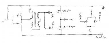
I saw your circuit #443, I do not understand the role of D1 D2 D3, how you bias upper SIT and low FET, not to mention the function of optocoupler.
Without U3, it is still functional I think, then how you get the bias voltage, why those D1 D2 D3 are back to back?
Maybe someday, a MLTL with 604 coaxial unit. For now, I am trying to get to know this Valencia.
I saw your circuit #443, I do not understand the role of D1 D2 D3, how you bias upper SIT and low FET, not to mention the function of optocoupler.
Without U3, it is still functional I think, then how you get the bias voltage, why those D1 D2 D3 are back to back?
Last edited:
just take source resistors for mosfet and try them
observe where output node is
regarding biasing , there is recently quoted explanation how M2 biasing is working , but can't recall in which thread ...... maybe M2
for your needs , no benefit in complicating it , at least not for now
observe where output node is
regarding biasing , there is recently quoted explanation how M2 biasing is working , but can't recall in which thread ...... maybe M2
for your needs , no benefit in complicating it , at least not for now
What I do not understand here.....
In my simulation the P channel shows the distortion and the SIT curve is "good"
Also my SIT vurve is the big one and the P channel curve the smaller one,
All vice versa...
No me was vice versa!
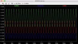
and I am just fighting with this effect in Spice. When I go higher with the current to 2A things get better.
Like this at 18W/8Ohm and 2A bias.
Attachments
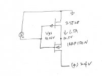
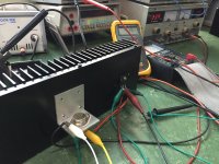
I took some time to wire these and tried. 2SJ28 and IRFP150N giving the voltage below, Vgs 4.19V @1.5A 24V.
But I do not know what the heaven these mean... It looks usable to me, with capacitors before and after the circuit.
Maybe I will wire another channel and see how it sounds.
But I do not know what the heaven these mean... It looks usable to me, with capacitors before and after the circuit.
Maybe I will wire another channel and see how it sounds.
Attachments
- Home
- Amplifiers
- Pass Labs
- Most Greedy Boy, of them all... or (there is no) DEFiSIT of Papa's Koans