X,
Wonderful work! And excellent subjectives. I'm always looking out for objective comments on the subjectives - always tricky!
You know I think if you replace the triplet of BF862 source followers with a single LU1014D with a 47R 5W resistor in the source to ground and a 47R stopper, I believe you will have back that pounding bass...... I would suggest lots of heatsinking on the LU, it will do around 1.9W of heat. The Rdson will be under 100 milliohms, and in fact you could drive a speaker directly.
That would make it simple, huh? Or maybe the CFP version?
Hugh
X,
Wonderful work! And excellent subjectives. I'm always looking out for objective comments on the subjectives - always tricky!
You know I think if you replace the triplet of BF862 source followers with a single LU1014D with a 47R 5W resistor in the source to ground and a 47R stopper, I believe you will have back that pounding bass...... I would suggest lots of heatsinking on the LU, it will do around 1.9W of heat. The Rdson will be under 100 milliohms, and in fact you could drive a speaker directly.
That would make it simple, huh? Or maybe the CFP version?
Hugh
This will solve my matching problem.

The nice thing about the triple BF862 is the rather low 50mA bias current flow which lends itself to battery powered portable use. With a single LU1014D as the Output stage - what is current using a 47R source resistor? Circa 200mA? Probably better suited as a desktop headamp then. I should do the LTSpice model - I can't figure out how to display the table of FFT coefs.
right click on the spice graph and click on 'view', show spice error log, I think.The nice thing about the triple BF862 is the rather low 50mA bias current flow which lends itself to battery powered portable use. With a single LU1014D as the Output stage - what is current using a 47R source resistor? Circa 200mA? Probably better suited as a desktop headamp then. I should do the LTSpice model - I can't figure out how to display the table of FFT coefs.
This will solve my matching problem.
Yes - that is one nice thing about single outputs. I have a bunch of small MOSFETs on the way to try out different ones. One is a depletion mode per suggestion of a member. It can probably be dropped straight in like a JFET and is self biasing. The N channel enhancement mode ones will need a bias circuit - which might be as simple as the voltage divider and small 47uF cap type that Hugh showed in the BF862/BD140 amp design. More sophisticated one might be a Zener/LED combo.
But having built the little Idss matching jig - and doing it with over a dozen BF862's - it wasn't bad. It can go pretty quickly if you are organized. I place them on sheet of paper in a grid and write the value measured (Idss etc). Then take wide strip of clear packing tape and tape over the little critters to seal them in. I use a small Xacto razor to poke a slit to take them out when ready to use.
I just ordered another qnty 50 BF862's for $10 - so they are very cost effective. For the sound quality and performance you get - there probably isn't a better deal in audio grade n channel JFETs right now.
Last edited:
How, Kovax?
Do you know the distortion of a LU1014D vis a vis a large triode in CF?
HD
My comment was made sitting on the shoulder of a true giant - Nelson Pass.
All the info can be found reading Zen variations 8 and 9 and First watt F3 amps and EUVL's DAO. I'm electrical engineering challenged myself.
AB comparison with 10 JFET amp
I wanted to see what the difference is between two amps with similar topologies and same JFETs in a side-by-side AB comparison. A quick re-cap for those new to thread...
The first amp is described here:
http://www.diyaudio.com/forums/head...f862-based-se-class-headamp-without-heat.html
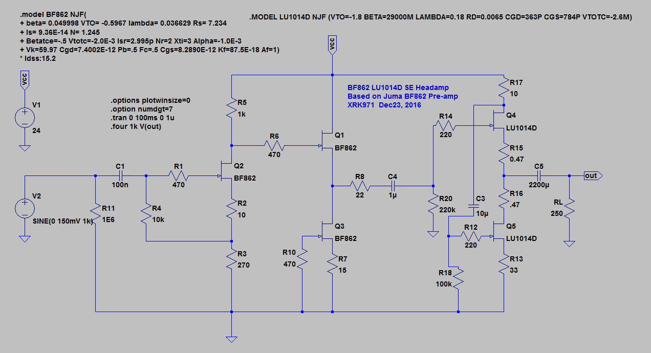
Schematic:
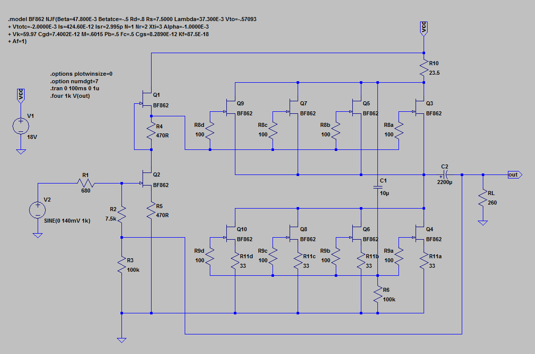
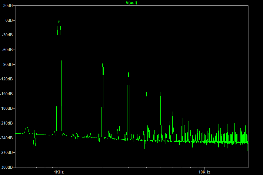
With a simulated FFT distortion profile that looks like this:
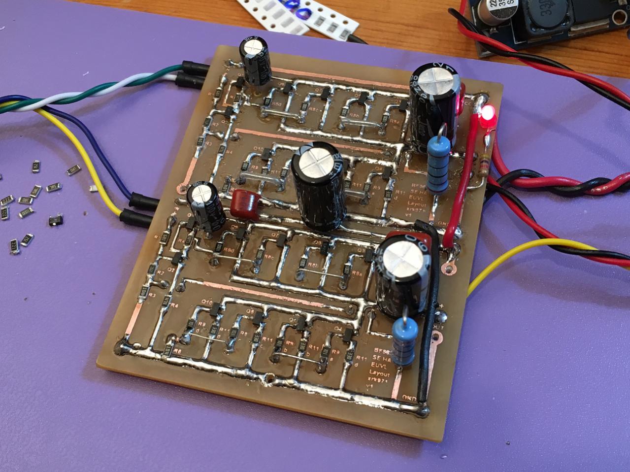
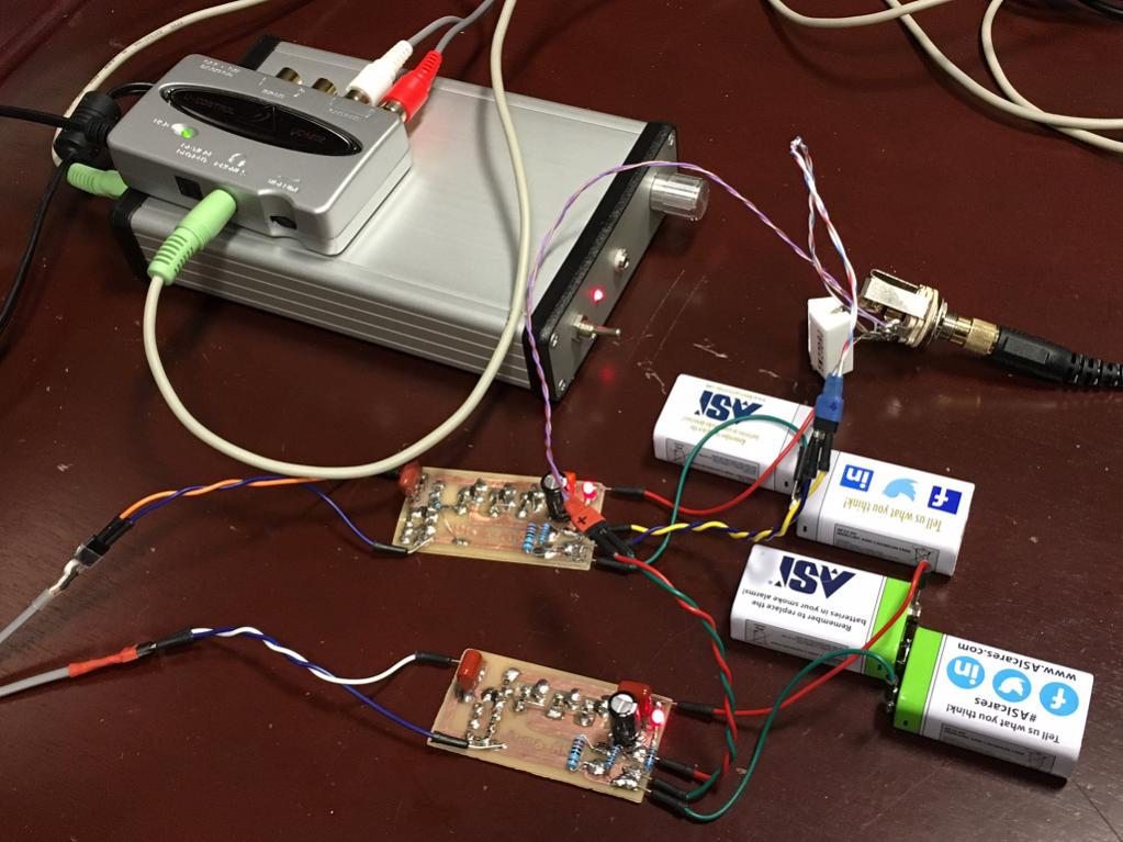
Built up looks like this - lots of devices:
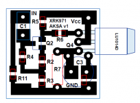
Compared to the simple 4 JFET proposed by Aksa as modification of Juma's excellent 3 JFET pre-amp:
Here is my AB test setup. I have to manually unplug and plug in headphone jack between two amps. Headphone is DT880-250ohm (chrome special edition). The source this time is a Behringer UCA202 USB with RCA outs going to the 4 JFET amp and the headphone outs going to the 10 JFET amp. Music tracks are various standbys I have listened to for years (jazz vocals, female pop, jazz trio with piano/bass/drums, rock, house hip-hop dance). I adjusted volume to be the same for both setups (adjusted by ear). Then after listening to a passage (20 seconds long typically), I quickly switch amps and repeat passage so that my memory is fresh.
Here are my subjective assessments.
Jazz vocals (Cassandra Wilson) 4 JFET amp: sounds excellent, very smooth, detailed highs, great mid range clarity and articulation. 10 JFET amp: almost the same but there seems to be a bit more depth in the mid range, a bit more shimmer in the highs (very slight). Overall, almost identical performance and if I did not do an AB comparison, would be tough to tell apart. The 10 JFET amp has more gain though so can get louder (I think there is a global feedback loop.
Pop vocals (Norah Jones, Come Away with Me) Both amps almost indistinguishable. The 10 JFET amp has a slight edge with midrange presentation - soundstage/imaging seems better but very subtle effect. On average though, very hard to tell the two amps apart.
Jazz trio (Chick Correa, Eddie Gomez, Paul Motian - Periscope): The 4 JFET amp seems to have drier presentation of drum kit - the cymbals, high hats, snare seemed to have less shimmer. Could be fact that there are no HD components above H3 and H3 is very small. Whereas the 10 JFET amp has a much richer predicted HD profile with decreasing components but they are there. The attack on the piano strikes and hard drum hits were more impactful on 10 JFET amp. I think this is simply because there is one extra JFET on the output which allows higher current for more headroom. I think overall I prefer the 10 JFET amp for jazz. But in a situation where portable battery use is needed, the 4 JFET gets darn close and I think is a more truer representation due to cleaner HD profile.
Rock (Nils Lofgren - Keith Don't Go): The 4 JFET amp has great articulation of the acoustic guitar plucks, excellent presentation of male vocals, overall balance and dynamics of guitar body slaps are excellent. Overall the 10 JFET amp is very similar but has an edge on dynamics where sound levels take excursions to 0dB like the crescendo at 4:40. The smaller 4 JFET amp seems to run out of steam here. It may be that a better battery might help as I measured the voltage rail - under class A load of 50mA it sags to 15.5v whereas the 10 JFET amp has a 3A smps wall wart, a DC step up, and a cap Mx. So perhaps a bit unfair.
For deep bass and overall dynamics and punchiness, I am using a YouTube collection here: https://www.youtube.com/watch?v=SjCMi9r3uS8
I know, gasp, YouTube for audio test tracks! Well for deep bass dance music, it sounds just fine.
The 10 JFET amp absolutely shines here - deep powerful bass, very sharp and clear highs. Really makes me tap my feet and want to move. Great dynamics, enveloping and head shaking with volume turned up. 4 JFET amp is about 85% there in bass authority and sounds excellent given it's a pair of cheap carbon 9v batteries. I would not mind listening to it for extended periods. Dynamics are very very good and I still want to move and dance along. So not too shabby at all.
So I think my final assessment is that for overall use and given portability and easy 9v battery adaptation, the 4 JFET amp rocks. For best impact and deep bass with huge dynamics, the 10 JFET amp has the advantage. I would not hesitate to recommend either amp to someone, although matching 8 JFET output devices vs 3 is much more of a challenge. I should note that I did not do extensive matching of JFETs on 10 JFET amp, other than measuring individual bias current on ea (independent source resistor) and swapping JFETs until currents were within 10%. If I did the true matching of measuring Idss and match that way, it may be even better.
Anyhow, hope this review was helpful.
I wanted to see what the difference is between two amps with similar topologies and same JFETs in a side-by-side AB comparison. A quick re-cap for those new to thread...
The first amp is described here:
http://www.diyaudio.com/forums/head...f862-based-se-class-headamp-without-heat.html
Schematic:
With a simulated FFT distortion profile that looks like this:
Built up looks like this - lots of devices:
Compared to the simple 4 JFET proposed by Aksa as modification of Juma's excellent 3 JFET pre-amp:
Here is my AB test setup. I have to manually unplug and plug in headphone jack between two amps. Headphone is DT880-250ohm (chrome special edition). The source this time is a Behringer UCA202 USB with RCA outs going to the 4 JFET amp and the headphone outs going to the 10 JFET amp. Music tracks are various standbys I have listened to for years (jazz vocals, female pop, jazz trio with piano/bass/drums, rock, house hip-hop dance). I adjusted volume to be the same for both setups (adjusted by ear). Then after listening to a passage (20 seconds long typically), I quickly switch amps and repeat passage so that my memory is fresh.
Here are my subjective assessments.
Jazz vocals (Cassandra Wilson) 4 JFET amp: sounds excellent, very smooth, detailed highs, great mid range clarity and articulation. 10 JFET amp: almost the same but there seems to be a bit more depth in the mid range, a bit more shimmer in the highs (very slight). Overall, almost identical performance and if I did not do an AB comparison, would be tough to tell apart. The 10 JFET amp has more gain though so can get louder (I think there is a global feedback loop.
Pop vocals (Norah Jones, Come Away with Me) Both amps almost indistinguishable. The 10 JFET amp has a slight edge with midrange presentation - soundstage/imaging seems better but very subtle effect. On average though, very hard to tell the two amps apart.
Jazz trio (Chick Correa, Eddie Gomez, Paul Motian - Periscope): The 4 JFET amp seems to have drier presentation of drum kit - the cymbals, high hats, snare seemed to have less shimmer. Could be fact that there are no HD components above H3 and H3 is very small. Whereas the 10 JFET amp has a much richer predicted HD profile with decreasing components but they are there. The attack on the piano strikes and hard drum hits were more impactful on 10 JFET amp. I think this is simply because there is one extra JFET on the output which allows higher current for more headroom. I think overall I prefer the 10 JFET amp for jazz. But in a situation where portable battery use is needed, the 4 JFET gets darn close and I think is a more truer representation due to cleaner HD profile.
Rock (Nils Lofgren - Keith Don't Go): The 4 JFET amp has great articulation of the acoustic guitar plucks, excellent presentation of male vocals, overall balance and dynamics of guitar body slaps are excellent. Overall the 10 JFET amp is very similar but has an edge on dynamics where sound levels take excursions to 0dB like the crescendo at 4:40. The smaller 4 JFET amp seems to run out of steam here. It may be that a better battery might help as I measured the voltage rail - under class A load of 50mA it sags to 15.5v whereas the 10 JFET amp has a 3A smps wall wart, a DC step up, and a cap Mx. So perhaps a bit unfair.
For deep bass and overall dynamics and punchiness, I am using a YouTube collection here: https://www.youtube.com/watch?v=SjCMi9r3uS8
I know, gasp, YouTube for audio test tracks! Well for deep bass dance music, it sounds just fine.
The 10 JFET amp absolutely shines here - deep powerful bass, very sharp and clear highs. Really makes me tap my feet and want to move. Great dynamics, enveloping and head shaking with volume turned up. 4 JFET amp is about 85% there in bass authority and sounds excellent given it's a pair of cheap carbon 9v batteries. I would not mind listening to it for extended periods. Dynamics are very very good and I still want to move and dance along. So not too shabby at all.
So I think my final assessment is that for overall use and given portability and easy 9v battery adaptation, the 4 JFET amp rocks. For best impact and deep bass with huge dynamics, the 10 JFET amp has the advantage. I would not hesitate to recommend either amp to someone, although matching 8 JFET output devices vs 3 is much more of a challenge. I should note that I did not do extensive matching of JFETs on 10 JFET amp, other than measuring individual bias current on ea (independent source resistor) and swapping JFETs until currents were within 10%. If I did the true matching of measuring Idss and match that way, it may be even better.
Anyhow, hope this review was helpful.
Attachments

Last edited:
You know I think if you replace the triplet of BF862 source followers with a single LU1014D with a 47R 5W resistor in the source to ground and a 47R stopper, I believe you will have back that pounding bass...... I would suggest lots of heatsinking on the LU, it will do around 1.9W of heat.
I almost forgot that I tried to do something like this already using Juma's preamp as input stage and the LU1014D in SE output with CCS. I posted it here:
http://www.diyaudio.com/forums/pass-labs/146310-bf862-preamp-49.html
However, Juma felt there were too many things wrong with it to even explain what I should do differently.
I suppose your two transistor version will be simpler and perhaps have a better sonic signature of mostly H2 and very low H3 and nothing else.
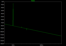
Here is the LTSpice sim of a single LU1014D for output. I adjusted the source resistor to 100R for about 100mA bias. The predicted FFT at 1.5v p-p output is quite good with THD of only 0.014%.
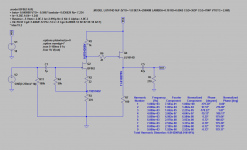
Schematic:
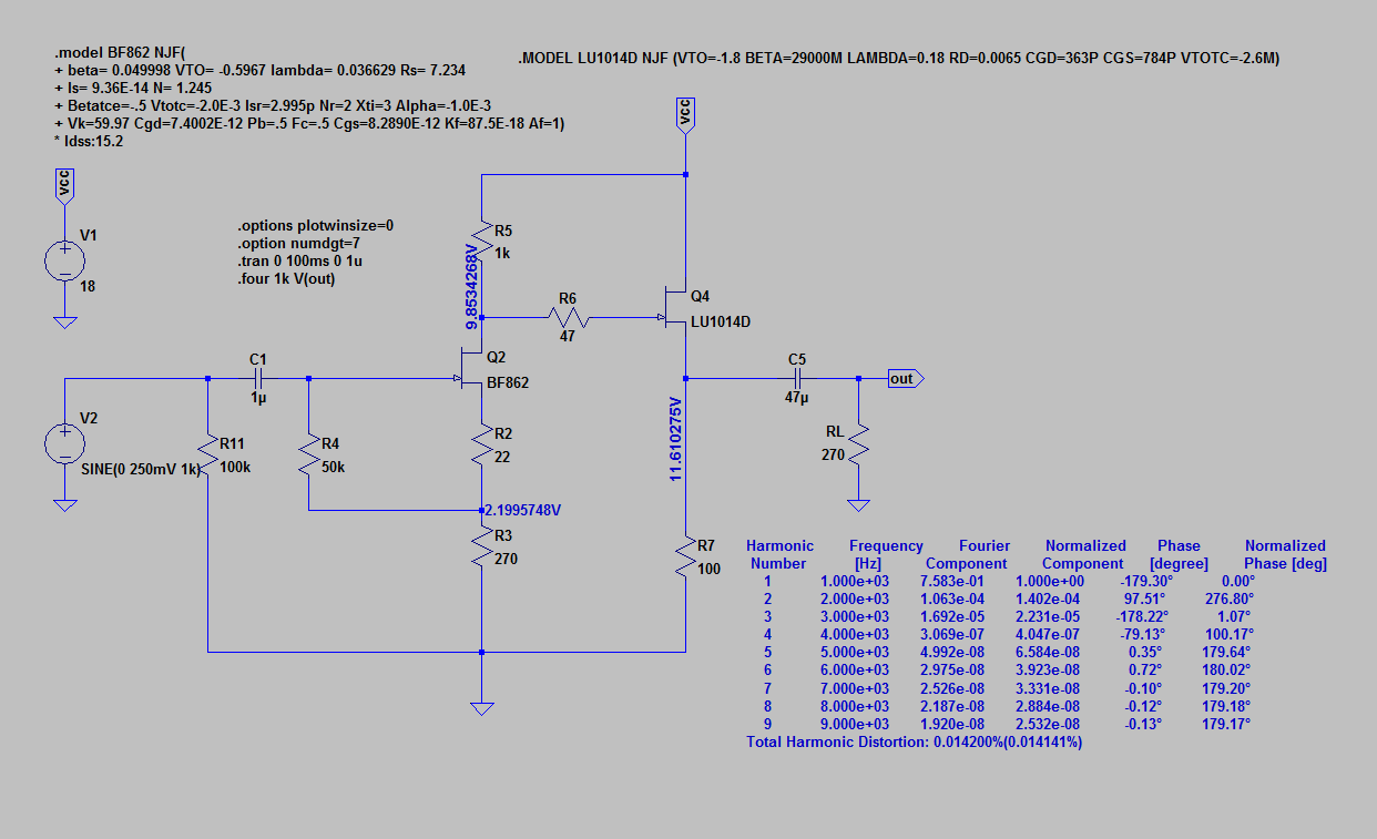
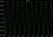
1k Sine wave at 1,5v P-P:

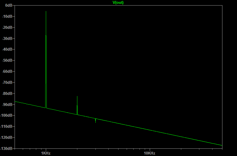
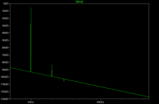
FFT:
For 60ohm cans, it is even better (THD is 0.010%):
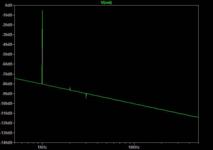
This suggests one should add parallel load resistors on the output to get 60R. So about a 70R resistor in parallel for 250ohms cans should reduce HD.
Not too shabby for a 2 transistor amp!
Schematic:
1k Sine wave at 1,5v P-P:
FFT:
For 60ohm cans, it is even better (THD is 0.010%):
This suggests one should add parallel load resistors on the output to get 60R. So about a 70R resistor in parallel for 250ohms cans should reduce HD.
Not too shabby for a 2 transistor amp!
Attachments
Last edited:
right click on the spice graph and click on 'view', show spice error log, I think.
Thanks, Prasi. Ok, how do I look at magnitude and phase plot?
Hi X,
Lots of work, thanks ! I've got to build your schematic on post 114.
Your 270 ohm FFT is quite amazing, reminds me of the AKSA 55 FFT which is my all time favorite amp. (Thanks Hugh)
Do you believe it's possible to get the same FFT results as the 270 ohm with the 60 ohm cans, i.e. a slight H2 increase would be nice ? I know it's sound like an odd request since the overall THD will be higher but I really enjoy the H2 sonic signature.
Thanks,
Eric
right click on schematic, edit simulation cmd, select AC analysis and run the sim.Thanks, Prasi. Ok, how do I look at magnitude and phase plot?
Hi X,
Lots of work, thanks ! I've got to build your schematic on post 114.
Your 270 ohm FFT is quite amazing, reminds me of the AKSA 55 FFT which is my all time favorite amp. (Thanks Hugh)
Do you believe it's possible to get the same FFT results as the 270 ohm with the 60 ohm cans, i.e. a slight H2 increase would be nice ? I know it's sound like an odd request since the overall THD will be higher but I really enjoy the H2 sonic signature.
Thanks,
Eric
Maybe add 200R resistor in series with output (this will also have effect of increasing Q of phones and may give deeper bass)? I know that playing around with resistor values on gate may have an effect. I will have to play with it.

- Home
- Amplifiers
- Headphone Systems
- MOSFET Source Follower Headamp