Hello everyone.
Months ago I built this amplifier using original schematics at Project 83 - MOSFET Power Follower
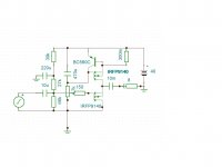
It sounded pretty well, and was first class A amp I've built. Unfortunately faulty tube preamp destroyed MOSFets (I hadn't soldered zeners). So I checked my drawer and found out that I have used all of N-Channel FETs, only P-Channel ones were there (9140 and 9240). I tried to change schematic, so P-Channel devices can be used. I would like that some more knowledgeable user would check attached schematic, if there is no some bad mistakes. I actually tried to simulate this circuit, and it worked, but I am still not sure.
Best regards, Arch.
Months ago I built this amplifier using original schematics at Project 83 - MOSFET Power Follower
It sounded pretty well, and was first class A amp I've built. Unfortunately faulty tube preamp destroyed MOSFets (I hadn't soldered zeners). So I checked my drawer and found out that I have used all of N-Channel FETs, only P-Channel ones were there (9140 and 9240). I tried to change schematic, so P-Channel devices can be used. I would like that some more knowledgeable user would check attached schematic, if there is no some bad mistakes. I actually tried to simulate this circuit, and it worked, but I am still not sure.
Best regards, Arch.
Attachments
Hello everyone.
Months ago I built this amplifier using original schematics at Project 83 - MOSFET Power Follower
It sounded pretty well, and was first class A amp I've built. Unfortunately faulty tube preamp destroyed MOSFets (I hadn't soldered zeners). So I checked my drawer and found out that I have used all of N-Channel FETs, only P-Channel ones were there (9140 and 9240). I tried to change schematic, so P-Channel devices can be used. I would like that some more knowledgeable user would check attached schematic, if there is no some bad mistakes. I actually tried to simulate this circuit, and it worked, but I am still not sure.
Best regards, Arch.
Dear Arch,
Since I have tested and modified various Follower schematics, I feel myself sure enough to state, that this your modification has nothing in common with the original Pavel's schematics, since in your modification the load is connected in parallel to the active device, rather than to the current source, like in Pavel's and many similar schematics (they are much more numerous than this your version). What you have drawn is actually the Ciuffolli's Follower schematics, almost completely. And I would encourage you in going along this your way of thinking. Why is it so, is not easy to formulate in few words, one should go along many lengthy discussions concened to this subject. Simulation wise, there are not much difference between the schematics with loads in parallel to CS and to active device. But, soundwise, the difference is very big.
Last edited:
Hello VladimirK.
You are right, I took a look at both schematics, and yep.. But well, I quickly soldered P2P version, and it works great. Unfortunately I can't check if I do mention an audible difference from original Pavel's Mosfet Follower, because original died (as I said in first post).
But one thing I mentioned - P-Channel (Ciufolli's) version is more sensitive to mains hum, so there is one more thing I took from Ciufolli's design - so called "Virtual battery". With this simple trick amplifier is dead quiet without source.
So, it works, and I am gonna let it play for few hours now")
You are right, I took a look at both schematics, and yep.. But well, I quickly soldered P2P version, and it works great. Unfortunately I can't check if I do mention an audible difference from original Pavel's Mosfet Follower, because original died (as I said in first post).
But one thing I mentioned - P-Channel (Ciufolli's) version is more sensitive to mains hum, so there is one more thing I took from Ciufolli's design - so called "Virtual battery". With this simple trick amplifier is dead quiet without source.
So, it works, and I am gonna let it play for few hours now
Hello VladimirK.
You are right, I took a look at both schematics, and yep.. But well, I quickly soldered P2P version, and it works great. Unfortunately I can't check if I do mention an audible difference from original Pavel's Mosfet Follower, because original died (as I said in first post).
But one thing I mentioned - P-Channel (Ciufolli's) version is more sensitive to mains hum, so there is one more thing I took from Ciufolli's design - so called "Virtual battery". With this simple trick amplifier is dead quiet without source.
So, it works, and I am gonna let it play for few hours now
I would propose, for further improvements, to change this your version to N-channel MOSFETs ("-" power supply), and to look around for transistors with better than IRFP ratio of Ciss/transconductance under working drain current and voltage. For OTL tube preamp, it is very tuff job to drive the gate of power MOSFET directly. I would look for a preamp with Rout around 100 Ohms and standing current at preamp's output stage around 20...40mA.
Last edited:
Ar4,
you might consider a power supply like this one:
The Class-A Amplifier Site - The Capacitance Multiplier
Regards,
you might consider a power supply like this one:
The Class-A Amplifier Site - The Capacitance Multiplier
Regards,
VladimirK, thank you for suggestions, gonna try some different FETs when I'll get them (student's life - saving ever cent ) About driving gate.. I am using hybrid cathode follower, it drives heavy loads quite fine.
Pavel, thank you for capacitance multiplier suggestion, I have used that one too, but somehow a bit modified "Virtual battery" circuit suits me better. No hum + kind of soft start. Also, thanks for "hint"
And I am sorry for misspelling your last name, unfortunately I can't find a way how to edit it.
) About driving gate.. I am using hybrid cathode follower, it drives heavy loads quite fine.Pavel, thank you for capacitance multiplier suggestion, I have used that one too, but somehow a bit modified "Virtual battery" circuit suits me better. No hum + kind of soft start.
Also, thanks for "hint" And I am sorry for misspelling your last name, unfortunately I can't find a way how to edit it.
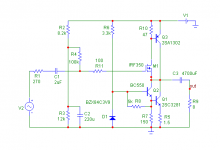
So I finally built this amplifier, stereo version, used 2xIRFP9240 for CCS and 1xIRFP9140 for current amplification per channel. Attached schematic shows exact components I used, except doubled CCS devices, they are "overlayed". And not gate protection yet (I obviously do not learn from my mistakes )
Using tube preamp, with MAX1771 SMPS, powered from 12V. There is a bit too much gain tho.
I simulated preamp+amp THD (16 harmonics), and TinaTi says - 0.023% @1kHz with 100mV input in tube preamp and 2.05V output. and 0.24227% @10kHz with 500mV input (resulting in 10.1V output). This is for 8ohm resistive load. Of course, in reality it differs, but I really enjoy the sound of amplifier, and I am not looking for 0,000001% THD, as I don't think I could even tell the difference between 0,5% or 0,01%
Conclusion - it works fine, I like it, and thanks to Pavel, thanks to Andrea, and thanks to Vladimir.
)Using tube preamp, with MAX1771 SMPS, powered from 12V. There is a bit too much gain tho.
I simulated preamp+amp THD (16 harmonics), and TinaTi says - 0.023% @1kHz with 100mV input in tube preamp and 2.05V output. and 0.24227% @10kHz with 500mV input (resulting in 10.1V output). This is for 8ohm resistive load. Of course, in reality it differs, but I really enjoy the sound of amplifier, and I am not looking for 0,000001% THD, as I don't think I could even tell the difference between 0,5% or 0,01%
Conclusion - it works fine, I like it, and thanks to Pavel, thanks to Andrea, and thanks to Vladimir.
Attachments
I had an observation, that if one uses an interconect cable between the preamp and the follower stage, then sound depends on where the interstage capacitor is installed. Better to install it at the follower stage, and to let the dielectric material, surrounding the cable core wire, be under high polarization voltage.
Next steps in evolution of my projects, were, to use an integrated amp arrangement with external power supply, and to apply some NFB of the current type. The last has added naturalness to bass reproduction, and the last effect is not due to lowering of Zout. Even with higher Zout the amp with current NFB sounds better in bass than original follower having lower Zout. This effect is clearly confirmed with both PMC EB1i and with Revel speakers. Also, bass improves by increasing output capacitance up to 30000uF (I used 47uF Obbligatto poly cap, 16x1000uF 50V Nichikon KZ, plus 2x10000uF Panasonic (the last two are separated by 0,05Ohms resistor, two 0,1 Ohms in parallel). Those who believe that better to use capacitorless output, are getting wrong, since they will need similar capacitor design on both + and - supply rails. With the Ciuffolli Follower arrangement such capacitor is needed in one place only, and it also provides speaker protection.
Next steps in evolution of my projects, were, to use an integrated amp arrangement with external power supply, and to apply some NFB of the current type. The last has added naturalness to bass reproduction, and the last effect is not due to lowering of Zout. Even with higher Zout the amp with current NFB sounds better in bass than original follower having lower Zout. This effect is clearly confirmed with both PMC EB1i and with Revel speakers. Also, bass improves by increasing output capacitance up to 30000uF (I used 47uF Obbligatto poly cap, 16x1000uF 50V Nichikon KZ, plus 2x10000uF Panasonic (the last two are separated by 0,05Ohms resistor, two 0,1 Ohms in parallel). Those who believe that better to use capacitorless output, are getting wrong, since they will need similar capacitor design on both + and - supply rails. With the Ciuffolli Follower arrangement such capacitor is needed in one place only, and it also provides speaker protection.
Last edited:
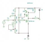
I've played around with P-Channel devices, so here is a schematic for those who hate capacitors at output. Actually I have nothing against capacitors, some kind of DC protection as bonus, but I wanted to try a capless version too. Pot and resistor combination might be changed.
Attachments
- Status
- This old topic is closed. If you want to reopen this topic, contact a moderator using the "Report Post" button.
- Home
- Amplifiers
- Solid State
- MOSFet Power Follower by Pavel Makura. P-Channel devices.