Marantz SR7000


The schematics and picture looks interesting. But "Marantz SR7000" is an audio-video receiver. What are the items you posted?
The schematics and picture looks interesting. But "Marantz SR7000" is an audio-video receiver. What are the items you posted?
Did you happen to notice he posted those images over a year ago?
Hello everybody.
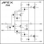
Going to make this HA5000 clone (attached) with J554/K2955 output stage.
But the PCB have some changes from photos and schematics provided by seller. It marked as V1.1. Power thansformer is toroid 2*16V AC, about 50W. Potentiometer is blue ALPS.
I need an advice
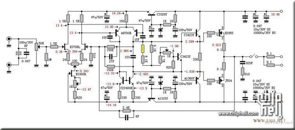
1.There is a variable resistor (2k). When starting the board, what is the safe position for them?
2.They are using ultrafast diodes in rectifier. Shouldn't them be shounted by caps?
attachments: seller image, schematics, actual board both sides
Going to make this HA5000 clone (attached) with J554/K2955 output stage.
But the PCB have some changes from photos and schematics provided by seller. It marked as V1.1. Power thansformer is toroid 2*16V AC, about 50W. Potentiometer is blue ALPS.
I need an advice
1.There is a variable resistor (2k). When starting the board, what is the safe position for them?
2.They are using ultrafast diodes in rectifier. Shouldn't them be shounted by caps?
attachments: seller image, schematics, actual board both sides
An externally hosted image should be here but it was not working when we last tested it.
An externally hosted image should be here but it was not working when we last tested it.
An externally hosted image should be here but it was not working when we last tested it.
Your schematic is difficult to read because it's so small.
From the schematic it looks like the trimmers are 1K not 2K, not that it really matters.
To be on the safe side, set the trimmers to their maximum value first. This should supply the least amount of current.
Better to start low and then go higher than the other way around.
From the schematic it looks like the trimmers are 1K not 2K, not that it really matters.
To be on the safe side, set the trimmers to their maximum value first. This should supply the least amount of current.
Better to start low and then go higher than the other way around.
- Status
- This old topic is closed. If you want to reopen this topic, contact a moderator using the "Report Post" button.