Well, since this is a small signal application, you can use small transistors. Bias current is a non-issue since it's small (current divided by hfe) and constant. HV bipolars are extremely easy to find.
Take a look at the circuit I used in the "SY Gets Jiggy" thread.
Take a look at the circuit I used in the "SY Gets Jiggy" thread.
Ok, i have made a cascode using bipolars to source ideally 1.1mA as a 12AX7 load.
It will be working into about 1Mohm.
It simulated ok i have attached the picture with the measurements on.
I have thought of a problem though, the Mcintosh amp was designed to put about 170V onto the tubes' plate, with this cascode i seem to get 260V across my 1M load?
Will this work (i am still studying electronics and havn't done this before)?
Cheers
Craig
Attachments
Where did the 1M resistor come from? I thought this was a load for a 12AX7 plate?
If that's the case, say the word and I'll sketch out a quick design for a 1.2mA source.
If that's the case, say the word and I'll sketch out a quick design for a 1.2mA source.
Sry i meant that 1M was the input impedance of the next stage, but this is in // with the triode the CCS sits on top of so i guess it doesn't look like 1M at all to the CCS.
If you could sketch one that would be great, Vs is 265V, i am replacing an anode resistor of 100K, Plate current was 1mA and plate voltage was 170V.
Is it worth current sinking the cathode follower at the output too?
Thanks a lot
Craig
If you could sketch one that would be great, Vs is 265V, i am replacing an anode resistor of 100K, Plate current was 1mA and plate voltage was 170V.
Is it worth current sinking the cathode follower at the output too?
Thanks a lot
Craig
Here's a sketch for a 1.25mA ccs suitable for your preamp. If you want to drop it to 1mA, change R1 to 1K. The reference string is set to pass 5mA through the LED voltage reference, which lowers its noise and impedance. You might want to bypass the LED with a cap- 470uF at 16V will be more than adequate.
The reference string can feed more than one ccs- if you're doing two, for example, all you need is a second pair of transistors and another R1. R2 should have a 2W rating; higher is better and wirewound will work fine. R2's value is not critical- a 47K will be just fine, as will a 51K.
Depending on your power supply, you might have to diddle the value of any series resistors to account for the extra 5mA of current burned up in the reference string. On the bright side, the LED gives a nice visual confirmation that the power supply is working. And if your supply drops under the additional 5mA, that will still be OK as long as the supply is 15 volts or more higher than the tube's plate voltage.
The transistor closest to the B+ rail does not need a high voltage rating- get a small signal PNP with a high hfe and ft. It's not critical. The transistor connected to the 12AX7 plate needs to have at least a 300V rating. If its power dissipation is about 1W or higher, it will be fine without a heatsink. As before, the particular type is not critical- use what's easy to find.
Attachments
SY, thanks very much that is excellent.
Regards to the 470uf cap, i wont be able to do this as my supply is tube regulated.
Is it ok to leave out caps in the bias? Would using a resistive divider allow me to connect a small cap as a low pass filter at the B+ transistors base.
Craig
Regards to the 470uf cap, i wont be able to do this as my supply is tube regulated.
Is it ok to leave out caps in the bias? Would using a resistive divider allow me to connect a small cap as a low pass filter at the B+ transistors base.
Craig
One thing about CCS's (sources or sinks) is keep capacitors out of them - lest you kill your PSRR (Power Supply Rejection Ratio) and end up with hum and noise from the rails 😉
The 470uF cap just goes in parallel with the LED reference, not the whole string. It will not degrade your supply or PSRR or anything else. All it will do is make sure that the dynamic impedance of the LED is nice and low.
No need to fool around with the bias string or any other complications- the ccs will work beautifully as-is. It does look too simple, but believe me, it will do the job. The 1M resistor in the next stage will be the limit to how high the load impedance can go (it's effectively in parallel with the ccs at AC).
No need to fool around with the bias string or any other complications- the ccs will work beautifully as-is. It does look too simple, but believe me, it will do the job. The 1M resistor in the next stage will be the limit to how high the load impedance can go (it's effectively in parallel with the ccs at AC).
SY i have built 4 of your cascode designs and all work nicely supplying 0.95mA into a 56K load!!
If i want to change the current to 0.3mA all i need to do it use a 3k3 resistor instead of 1K at the emitter of the Transistor closest to the B+ right?
If i calculate the CCS current correctly will the plate voltages be at what they were had i set the current with a resistor, 170/160V?
Thanks
Craig
If i want to change the current to 0.3mA all i need to do it use a 3k3 resistor instead of 1K at the emitter of the Transistor closest to the B+ right?
If i calculate the CCS current correctly will the plate voltages be at what they were had i set the current with a resistor, 170/160V?
Thanks
Craig
Yes, that's exactly right. It's just the reference voltage (1.7 for a red LED) minus Vbe for the transistor (typically 0.7V) divided by the desired current. The plate voltage will depend on both the set current and the grid-cathode bias. You can predict it from the tube characteristic curves.
If you want to have fun, replace the emitter resistor with a trimpot. You can spend days playing with the effect of current on distortion and bandwidth. Your wife will take up with your next door neighbor, your kids will forget you, but you'll have a totally studly circuit.
If you want to have fun, replace the emitter resistor with a trimpot. You can spend days playing with the effect of current on distortion and bandwidth. Your wife will take up with your next door neighbor, your kids will forget you, but you'll have a totally studly circuit.
I have put the 0.3mA ccs and the 1mA ccs into my circuit and measured the anode voltages, the 0.3mA ccs runs straight to 165V which is ok.
But the 1mA CCS goes to the full supply then down to 90 odd volts then up again and seems to slowly home in to about 160V over about a minute?
is this normal?
I have both CCS's running from one bias string with a 470uf 10V cap accross the LED.
Craig
But the 1mA CCS goes to the full supply then down to 90 odd volts then up again and seems to slowly home in to about 160V over about a minute?
is this normal?
I have both CCS's running from one bias string with a 470uf 10V cap accross the LED.
Craig
correction: the 1mA ccs goes to 145v (not 165V) once stabilised, it used to be 170V with resistors.
I have tried increasing the current allowed into the 265V line, it is now 20mA, (was 15mA), so the regulators are left with ~14mA.
It didnt stop the current source volatge swinging all over the place.
The wierd thing is that the current through the cahode resistors is right and remains constant. even theough the anode voltage is all over the place.

It didnt stop the current source volatge swinging all over the place.
The wierd thing is that the current through the cahode resistors is right and remains constant. even theough the anode voltage is all over the place.
Make sure that the bias arrangement for the tubes gives the right Vgk for the desired current/anode voltage.
Yes, the current and voltage at the cathode is as it should be, 0.75V for the 1mA triode and 2V for the 0.3mA triode.
Giving 0.915mA and 0.27mA.
Giving 0.915mA and 0.27mA.
Dumb suggestion: check your grid connections. If you could post a sketch of exactly what you've got setup, including series resistors from the power supply, that might be helpful for remote troubleshooting.
BTW, at the bias voltages you named, for the 0.3mA version, the tube curves suggest that you need 180V on the plate. That means at least 200-210V of supply.
My power supply is 377V DC branching off to two 5K resistors one 5K resistor goes to a stack od 2xVR150's/0D3's which form my 300V rail.
The other 5K goes to An 0C3/0D3 stack which forms my 265V rail.
Both rails have 0.033uf of capacitance ofter the regulators.
Here is my circuit:
Thanks
Craig
The other 5K goes to An 0C3/0D3 stack which forms my 265V rail.
Both rails have 0.033uf of capacitance ofter the regulators.
Here is my circuit:
Thanks
Craig
Attachments
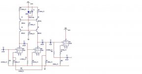
OK, it looks like the open loop gain is about 10,000, which will be an interesting exercise to try to stabilize. If I had to guess, you've got some motorboating or oscillation going on. Just for giggles, drop the coupling cap (looks like C3) by a factor of ten. The value is a bit small for me to read, but if it's 100nF, substitute a 10nF.
Second thing to do is to add some lead compensation. For experiment, stick 100pF across the feedback resistor (R12?). If you've got high frequency oscillation from the high feedback factor (like 60+dB!), that may calm it down a bit.
Second thing to do is to add some lead compensation. For experiment, stick 100pF across the feedback resistor (R12?). If you've got high frequency oscillation from the high feedback factor (like 60+dB!), that may calm it down a bit.
One more thing- the Miller capacitance of the second stage will cause quite a drastic HF rolloff from the first stage. Keep this in mind as you sort out the stability issues.
- Status
- Not open for further replies.
- Home
- Amplifiers
- Tubes / Valves
- MOSFET current source as triode load