I have tried a few searches on the site but can find no threads on single MOSFet Class A amps with inductive loading. Has anyone successfully done this and can tell me about it and what they did? Any schematics? Should this continue as a new thread?
I have built my own single MOSfet amp with resistive loading but understand inductive in the source leg can be achieved.
I have built my own single MOSfet amp with resistive loading but understand inductive in the source leg can be achieved.
yes
I have seen schematics of a circuit here at diyaudio.com
with use of inductors in outputstage, to increase power
I do not remember if it was MOSFET and/or single end, but is probable
topic name was 'My Class A' or something like that
maybe someone else can search and find it
")
I have seen schematics of a circuit here at diyaudio.com
with use of inductors in outputstage, to increase power
I do not remember if it was MOSFET and/or single end, but is probable
topic name was 'My Class A' or something like that
maybe someone else can search and find it
I found it!
Topic by: Circlotron
Thread: My first ever Class A amp.
MOSFET Class A with inductor loaded output stage.
Schematic: MOSFET Inductor Output
Enjoy!
This thing is nominally a 50 watt per channel stereo setup with a source follower output stage and an inductor in the source lead.
It runs a 28 v rail with 3.5 amps current so that's about 100w dissipation.
The advantage of using an inductor is that you only need half the supply voltage because the inductor will swing the missing half rail for you.
Therefore the efficiency is at best a horrible 50% rather than a woeful 25%.
The downside is that suitable inductors are heavy and expensive.
But I already had two of them so that was lucky.
Topic by: Circlotron
Thread: My first ever Class A amp.
MOSFET Class A with inductor loaded output stage.
Schematic: MOSFET Inductor Output
Enjoy!
mhouston said:I have built my own single MOSFET amp with resistive loading
but understand inductive in the source leg can be achieved.
As far as I can undestand
you should be able to quite easy convert that amplifier, you have there,
to use a large inductor for load, instead of power resistor.
Gudd Lock!
Re: Re: MOSFet Class A SE with inductive loading.
So my 15ohm load resistor in the drain can be swapped for an inductor. Sounds too simple. Care to make a quantitive call for the inductance value? And are we talking 60mh or 10mh.
lineup said:
As far as I can undestand
you should be able to quite easy convert that amplifier, you have there,
to use a large inductor for load, instead of power resistor.
Gudd Lock!
So my 15ohm load resistor in the drain can be swapped for an inductor. Sounds too simple. Care to make a quantitive call for the inductance value? And are we talking 60mh or 10mh.
Re: Re: Re: MOSFet Class A SE with inductive loading.
I have no idea. I am not too good with inductors myself.
But you can get a hint from Circlotron schematic.
He has single supply 28V and 3.5A bias in MOSFET.
He uses 85mH in parallell with 8 Ohm speaker.
If I were you, I should read all his thread (see my link).
Maybe you find out some formula or way how to decide inductor value/size.
Circlotron is active, maybe he will join in to assist.
Circlotron, Last seen online: 22.02.06 10:41 AM (Today)
mhouston said:So my 15ohm load resistor in the drain can be swapped for an inductor.
Sounds too simple.
Care to make a quantitive call for the inductance value?
And are we talking 60mh or 10mh.
I have no idea. I am not too good with inductors myself.
But you can get a hint from Circlotron schematic.
He has single supply 28V and 3.5A bias in MOSFET.
He uses 85mH in parallell with 8 Ohm speaker.
If I were you, I should read all his thread (see my link).
Maybe you find out some formula or way how to decide inductor value/size.
Circlotron is active, maybe he will join in to assist.
Circlotron, Last seen online: 22.02.06 10:41 AM (Today)
Hugh Dean drew a MOSFet output stage with a choke in the source leg for me. His calcs. produced a 63mh unit at about 2A. I’m just trying to find out who else has been down this path. A Hammond 10mh 5A choke cost me $AU53.
I can get chokes wound but at this size (and I need two) the cost may out-weigh the benefit. I would like to try with no voltage stage before so a single fet (I’m using the 2sk1058) and inductive loaded. I realise the power will be well down but I have not found this a problem in the past.
I can get chokes wound but at this size (and I need two) the cost may out-weigh the benefit. I would like to try with no voltage stage before so a single fet (I’m using the 2sk1058) and inductive loaded. I realise the power will be well down but I have not found this a problem in the past.
mhouston said:Hugh Dean drew a MOSFet output stage with a choke in the source leg for me. His calcs. produced a 63mh unit at about 2A. I’m just trying to find out who else has been down this path. A Hammond 10mh 5A choke cost me $AU53.
I can get chokes wound but at this size (and I need two) the cost may out-weigh the benefit. I would like to try with no voltage stage before so a single fet (I’m using the 2sk1058) and inductive loaded. I realise the power will be well down but I have not found this a problem in the past.
Hammond ... hmm, yeah
When looking for good Chokes for SolidState power amplifiers
we could turn to Tube Valve stuff. They know these things.
But is far from impossible to build your own good COILS
for Inductive loaded Class A amp output stages.
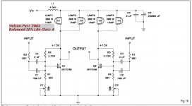
For example Nelson Pass is good with inductor construction.
His ZEN Lite uses a lamp light BULB as load for Class A.
Light bulbs are somewhat inductive ...
Zen Variations - Part 1: Zen-lightenment by Nelson Pass
(c) 2001, Nelson Pass
http://www.passdiy.com/pdf/zenlite.pdf
Attachment shows a more advanced variant:
Balanced Zen Lite with four 300 Watt Light Bulbs
Attachments
Hi Lineup!
There is the ZV7 with choke loading.
Tyimo
Sorry, but is it not a good example, because He used the bulbs as resistive loads.His ZEN Lite uses a lamp light BULB as load for Class A.
Light bulbs are somewhat inductive ...
There is the ZV7 with choke loading.
Tyimo
Tyimo said:Hi Lineup!
Sorry, but is it not a good example, because He used the bulbs as resistive loads.
There is the ZV7 with choke loading.
Tyimo
Hi Tyimo.
Yes, you are right.
I wrote in my post ... light bulbs are somewhat inductive.
Nelson Pass in his article ( the Zen Lite PDF )
discusses several ways, loads for Class A single end outputs:
... like constant current source, resistor etc.
This is valid reading if you are considering alternative ways of doing SE Class A.
Regars old friend Tyimo
Nice to meet you.
Lineup
Hi Lineup!
Nice to see you too!
Here is a thread for the ZV7-T:
http://www.diyaudio.com/forums/showthread.php?s=&threadid=75722
Greets:
Tyimo
Nice to see you too!
Here is a thread for the ZV7-T:
http://www.diyaudio.com/forums/showthread.php?s=&threadid=75722
Greets:
Tyimo
V for I
I have seen so much about constant I in the active end of amps with relation to Fets and Valves. Yes sometimes in the load/collector/drain end and others in the cathode end.
OK, here is a simple challenge, give me a single active component amp (e.g one Fet) where a constant voltage source in employed. My guess is it should be bipolar based.
Any takers?? Give me the cct.
Christer said:Chokes on the collecter used to be a standard method in textbooks, at least it is in my 40 year old book.
I have read where some builders would rather use trannies instead of caps to couple sections/stages (inter-stages) of an amp because (they claim) the trannies impart less of a signature than caps. So does any one have a very simple two stage power amp cct. employing trannies at the inert-stage point using SS devices?
mhouston said:
I have read where some builders would rather use trannies instead of caps to couple sections/stages (inter-stages) of an amp because (they claim) the trannies impart less of a signature than caps. So does any one have a very simple two stage power amp cct. employing trannies at the inert-stage point using SS devices?
Very few modern designs need the cap between stages. They are usually DC-coupled internally, and often also at input and/or output.
I think most SS amps with transformers are designs that were originally attempts to copy existing tube amps.
For a single mosfet SE amp, as the original Zen from www.Passdiy.com , the magic number for the inductor is around 80mH.
Magura
Magura
- Home
- Amplifiers
- Solid State
- MOSFet Class A SE with inductive loading.