What are you using for VAS transistor?
I'm using bf869 in one channel and ksc3503E in the other.
BF471
Hi terry,
BD139 in VAS is not the best because it has high capacitance,
BF471 is an old Philips part, hard to find NOS, use a KSC3503, not much better in current production these days.
Good one Thimios, I had to look up what a BF869 was, old TO-202, that goes way back.
Basically for VAS, you want a bjt that was used for high definition CRT applications.
Sanyo made a few of them too.
Last edited:
Hi terry,
BD139 in VAS is not the best because it has high capacitance,
BF471 is an old Philips part, hard to find NOS, use a KSC3503, not much better in current production these days.
Good one Thimios, I had to look up what a BF869 was, old TO-202, that goes way back.
Basically for VAS, you want a bjt that was used for high definition CRT applications.
Sanyo made a few of them too.
Exactly, BF869G is salvaged from a collor t.v RGB amplifier.
Hi terry,
i see that you are getting the hang of pcb layout, have you tried ltspice, it can give insight into the behavior of these designs and sometimes identify problems. Even just figuring out bias V/I and static power helps in design. ltspice, schematic, layout all part of analog design these days and all for free except the parts.
Is that the design as in post #1195, shown as a ltspice .asc file?
Last edited:
I can't understand why Terry is in troubles.
Mine is playing wonderful in a set of cheap speakers.
I think that is a simple,cheap. very good sounding amplifier.
Unfortunately English isn't my first language to explain in details how the sound is.
It is like organs and voices come more near to you.
Another good feeling is that you can hear good strong bass even when listen in low levels.
Try it, it is a must!
Last edited:
What bias setting are you using?I made 32 pcbs, 8 mos200 already playing in old rebuilding amplifiers without troubles. Sound very nice with good strong bass.
I can't understand why Terry is in troubles.
Mine is playing wonderful in a set of cheap speakers.
I think that is a simple,cheap. very good sounding amplifier.
Unfortunately English isn't my first language to explain in details how the sound is.
It is like organs and voices come more near to you.
Another good feeling is that you can hear good strong bass even when listen in low levels.
Try it, it is a must!
My Main problem is offset. I can't seem to get the offset to settle at a low value. Mains voltage changes it greatly. I have KSC3502 in now for the VAS. I haven't hooked up a speaker yet because of the offset. I know 70mV isn't a lot but I just think it should be able to go lower.
70 mV is acceptable.My Main problem is offset. I can't seem to get the offset to settle at a low value. Mains voltage changes it greatly. I have KSC3502 in now for the VAS. I haven't hooked up a speaker yet because of the offset. I know 70mV isn't a lot but I just think it should be able to go lower.
Hook up a test speaker.
Try a different 556b pair,may be get better offset
Last edited:
What bias setting are you using?
20mA amplifiers work in caffe bars as PA.
I suggest you to made TP2 preamplifier.
Attachments
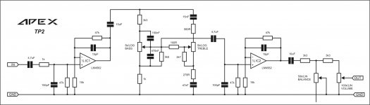
Thanks Mile.20mA amplifiers work in caffe bars as PA.
I suggest you to made TP2 preamplifier.
")
I think I have oscillation problems. I had both channels running with <30mV offset with input shorted. All looked OK so I hooked up some speakers and music to the input. As soon as I switched on the power the outputs shorted and blew the output resistors of my FX100 PSU. Unfortunately, My test equipment is not functioning correctly so I can't easily troubleshoot it. I'm going to sack this. Maybe I'll try again later when I get my equipment sorted.
Terry, just two things.I think I have oscillation problems. I had both channels running with <30mV offset with input shorted. All looked OK so I hooked up some speakers and music to the input. As soon as I switched on the power the outputs shorted and blew the output resistors of my FX100 PSU. Unfortunately, My test equipment is not functioning correctly so I can't easily troubleshoot it. I'm going to sack this. Maybe I'll try again later when I get my equipment sorted.
Solder the separate signal gnd to power supply 0v, very critical.
If this isn't well contact the 50v rail is present on the output and a speaker short the output.
Second, what is the bias?
Higher than 100mV is danger.
Use your simulation program to find the max bias that is safe.
Mile, can you answer what is the max safe bias setting?
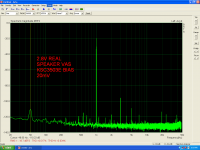
THD strongly depend from bias setting.
I will post results soon.
Hi terry,
BD139 in VAS is not the best because it has high capacitance,
It depends on the circuit. Most amps require the addition of capacitance to the VAS for stability, so a few extra pF in the VAS transistor is irreverent.
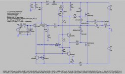
Ltp current is critical and must be about 3mA (Rail voltage 56V/(18k+1.2k)=2.9mA). If you use 35V replace 18k with 10k for different rail voltage you must calculate 18k resistor becouse there is no CCS. VAS current must be about 5mA, also there is no CCS (Rail voltage 56V/(6,8k+6,8k)=4,1mA) for different rail voltage you must calculate resistors value instead 6,8k. If ltp current is to low VAS transistor stop conducting and there is rail voltage on amp output. I have no stability problem evan with capacitive load (piezo driver).
I'm sure others are also thinking this needs a bit of adjustment. Adding a current mirror gets rid of any sensitivity to supply voltage, ie no parts changes required, de-thumps the on-off, and improves THD by about 5x. This does require adding a compensation cap on the VAS for stability and I used a 150V VAS transistor which makes little difference to simulation. I made the VBE resistors a little more realistic/easy and added a small -V filter for the front end.
Attachments
Last edited:
I'm sure others are also thinking this needs a bit of adjustment. Adding a current mirror gets rid of any sensitivity to supply voltage, ie no parts changes required, de-thumps the on-off, and improves THD by about 5x. This does require adding a compensation cap on the VAS for stability and I used a 150V VAS transistor which makes little difference to simulation. I made the VBE resistors a little more realistic/easy and added a small -V filter for the front end.
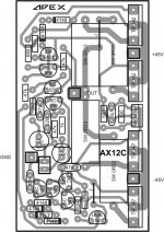
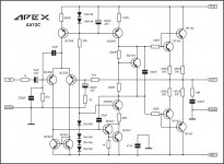
Nice, start to look like AX12C.
Attachments
 v
v
I have a +/-50v power supply.Ltp current is critical and must be about 3mA (Rail voltage 56V/(18k+1.2k)=2.9mA). If you use 35V replace 18k with 10k for different rail voltage you must calculate 18k resistor becouse there is no CCS. VAS current must be about 5mA, also there is no CCS (Rail voltage 56V/(6,8k+6,8k)=4,1mA) for different rail voltage you must calculate resistors value instead 6,8k. If ltp current is to low VAS transistor stop conducting and there is rail voltage on amp output. I have no stability problem evan with capacitive load (piezo driver).
I have 16k in ltp so 2.9mA ltp current
I have 5k6+5k6 in the VAS so current is 4.46mA.
I haven't check using oscilloscope but never smelled a hot zobel.
Last edited:
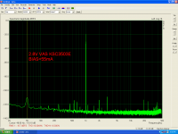
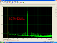
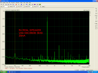
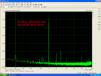
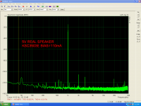
How the bias setting affect the THD.
I will ask again.
Using +/-50v power supply.
What is the max safe value for bias setting?
I will ask again.
Using +/-50v power supply.
What is the max safe value for bias setting?
Attachments
Last edited:
- Home
- Amplifiers
- Solid State
- MOSFET Amplifier IRFP240/IRFP9240