Hi guys,
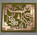
I could not get MOS200 to work.
1. Offset ~200mV with shorted input.
2. Positive rail draws a little more that the negative with shorted input.
3. No sound when connecting a source and a test speaker, positive rail draws much more than negative.
Any clues?
I could not get MOS200 to work.
1. Offset ~200mV with shorted input.
2. Positive rail draws a little more that the negative with shorted input.
3. No sound when connecting a source and a test speaker, positive rail draws much more than negative.
Any clues?
Attachments
Hi guys,
I could not get MOS200 to work.
1. Offset ~200mV with shorted input.
2. Positive rail draws a little more that the negative with shorted input.
3. No sound when connecting a source and a test speaker, positive rail draws much more than negative.
Any clues?
Post voltage measurements on transistors pins.
Post voltage measurements on transistors pins.
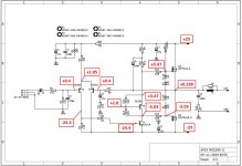
Hi Mile,
Here is my MOS200 measurement chart.
Thanks for your help.
Jacques
Attachments
absolutely no sound would indicate incorrect pins on one of the transistors, or dead transistor
I verified all components, pinning and changed all the transistors, same result unfortunately.
The voltage measurements are not ideal but very close to the correct values so I suspect that it is working and you have a problem with input or output connection, or you are measuring the wrong channel etc.
My lab PSU is in current limiting mode @200mA for initial testing. With a load connected, the positive rail collapses. This should not happen.
do the math
Then the output has to be at least 8 Ohms *0.2A = 1.6VDC, not 0.16V.
It's also possible that your PS limit is ~20mA and not 200mA.
Something is not as advertised.
This would happen if the LTP and VAS was not working.
Be sure D6 is not backwards and you have 10V on it.
I think R5 and R6 should be about 2k2. 3k3 is starving the LTP a bit.
Hi Steveu,
The posted values are obtained with a shorted input and without load with PSU +/-25V 0.2A limiting. In these conditions, it draws +0.016A and -0.013A.
With a load connected only the positive rail drops to 4.5V indicating overcurrent which I think is not a healty behaviour for this class amp.
The D6 zener is positioned as in the schematics and carries 9.54V, not 10.
Thanks for your help.
Jacques
DC latchup
I suspect you have a DC latch-up caused by the PS collapse. Try powering R6 from a separate supply and see what happens, or boost the current limit up to say 500mA.
This would not happen if the circuit used a current mirror but then you would have to add a compensation cap to keep the extra gain stable... etc.
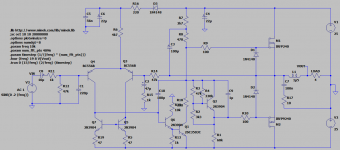
This circuit is as bit too simple resulting in issues that a few extra penny transistors could easily fix. If I spend the money to build the expensive parts, I would make something like this:
I suspect you have a DC latch-up caused by the PS collapse. Try powering R6 from a separate supply and see what happens, or boost the current limit up to say 500mA.
This would not happen if the circuit used a current mirror but then you would have to add a compensation cap to keep the extra gain stable... etc.
This circuit is as bit too simple resulting in issues that a few extra penny transistors could easily fix. If I spend the money to build the expensive parts, I would make something like this:
Attachments
I suspect you have a DC latch-up caused by the PS collapse. Try powering R6 from a separate supply and see what happens, or boost the current limit up to say 500mA.
This would not happen if the circuit used a current mirror but then you would have to add a compensation cap to keep the extra gain stable... etc.
This circuit is as bit too simple resulting in issues that a few extra penny transistors could easily fix. If I spend the money to build the expensive parts, I would make something like this:
This amp in its bare simplicity was supposed to be a fun projet for a lockdown weekend with all the components already at hand.
I didn't have high expectations to start with.
I am sure there's better designs out there with CCS and current mirrors and I have already built several.
I'll keep fiddling with this one for a little while hoping to learn a few things with the help of all the experts here.
I think the amp will work if you connect the speaker after it powers up. The problem is that the VAS will not come on until the +V is at least ~8VDC so if the speaker is connected the outputs have only the pull-up resistor bootstrap so they try to put +V-4V (vto~=4V) onto the speaker until the LTP and the VAS starts working. If the supply is limited to less than say (8-4)V/8 Ohms=~500mA then the LTP +VAS will never start. And, yes, this amp will make a huge turn-on thump.
Last edited:
I think the amp will work if you connect the speaker after it powers up. The problem is that the VAS will not come on until the +V is at least ~8VDC so if the speaker is connected the outputs have only the pull-up resistor bootstrap so they try to put +V-4V (vto~=4V) onto the speaker until the LTP and the VAS starts working. If the supply is limited to less than say (8-4)V/8 Ohms=~500mA then the LTP +VAS will never start. And, yes, this amp will make a huge turn-on thump.
Hi Steveu,
Well it sort of works!
You are right: by increasing the current limit the amp starts and plays most of the times at turn on. In some cases though the positive rail still drops to a few volts and no sound is produced.
When playing 'normally' the amp still draws asymmetric current : 0.059A and 0.009A at +/-35V respectively. Could this be fixed?
There is absolutely no startup thump.
Thanks for helping,
Jacques

Asymmetric current draw is not a real problem but it's probably due to DC offset which may be a real problem. The best solution to DC offset is to balance the LTP current (and base resistors), which is what a current mirror does well. But a current mirror adds gain which would probably make the amp unstable unless you add a compensation cap.
A current mirror also makes the LTP(+VAS) operational with very little current and therefore operate with very little rail voltage.
Another way to get the LTP+VAS working asap is a CCS for the LTP, and it is an active filter (of the rail ripple voltage) that does not have much delay on start-up. A CCS that uses a LED or Zener has a higher voltage drop so it requires a higher rail voltage before the circuit is operational.
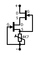
JFETs make a great CCS but they are unpredictable so you have to select parts, but the circuit is dead simple so it's a good choice for mods. Start with a JFET with IDS > the CCS and select a source resistor that gives you the required CCS.
But a CCS alone will probably not fix the offset unless you set the CCS to exactly 2X the current in each LTP transistor, which you could do by tweaking the source resistor.
The resistor in series with the VAS base is used instead of a compensation cap on the VAS but it complicates the LTP current calculation.
A current mirror also makes the LTP(+VAS) operational with very little current and therefore operate with very little rail voltage.
Another way to get the LTP+VAS working asap is a CCS for the LTP, and it is an active filter (of the rail ripple voltage) that does not have much delay on start-up. A CCS that uses a LED or Zener has a higher voltage drop so it requires a higher rail voltage before the circuit is operational.
JFETs make a great CCS but they are unpredictable so you have to select parts, but the circuit is dead simple so it's a good choice for mods. Start with a JFET with IDS > the CCS and select a source resistor that gives you the required CCS.
But a CCS alone will probably not fix the offset unless you set the CCS to exactly 2X the current in each LTP transistor, which you could do by tweaking the source resistor.
The resistor in series with the VAS base is used instead of a compensation cap on the VAS but it complicates the LTP current calculation.
Some replace the R3 resistor at the bottom of the LTP with a trimpot (see post #1357 above).
I will try that to balance the LTP before playing with CCS in Ltspice simulations when I get some free time.
A few years back with some help, I have added to an amp the double J112 JFET CCS below at ~5mA if I remember well, would it work here?
I will try that to balance the LTP before playing with CCS in Ltspice simulations when I get some free time.
A few years back with some help, I have added to an amp the double J112 JFET CCS below at ~5mA if I remember well, would it work here?
Attachments
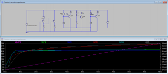
current constant circuits
Attached is a comparison of a few common constant current circuits. If the bjt circuits have a constant bias source, then the first two bjt are the best and reach the regulation current with only a couple volts, but we are concerned about supply ramp-up where the bias is also ramping up.
The Jfet circuits do not require any bias current and perform well, the two JFET circuit being a bit more flat but more complicated. I would go with the single Jfet circuit.
The LED circuit is just poor.
Attachments
- Home
- Amplifiers
- Solid State
- MOSFET Amplifier IRFP240/IRFP9240