Hi, I am doing a full upgrade on my Moscoed 300 and created a problem. As part of the upgrade I am hard wiring to the circuit board. By mistake I cut off one side of the connector from the switch to the transformer. It is a six connector that uses four of the six. If someone can let me know what the two white wires and two dark wires connect to on the transformer it will be greatly appreciated.
Thanks,
Ron
Thanks,
Ron
No, I have never seen a schematic for the power supply anywhere. I was hoping somone can just look at their unit and tell me the colors from the tranformer that correspond to the other side of the connector. I had to move the transformer over as I replaced the soda can caps with 25,000uf Sprague computer grade and they were too tall for the chassis.
I have two MOSCODE 300s so let me take a look...
Aha! - Yes, the there are two primary windings wired in parallel for 120V operation. Here are the color codes:
Light wire: yellow-white + black-white
Dark wire: red + black red
Before you connect, make sure you measure the primaries though. They should show roughly the same value in pairs.
Hope this helps.
D.
Do you have a schematic? I have a schematic for the audio portion only no power supply.
Craig
Craig,
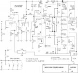
Do you have the ability to scan that schematic? I just did an upgrade on a 300 I have and I want to align the amp properly. Each channel has 2 pots in parallel to each other similar to the attached schematic that can be found out on the web for the 300. The attached schematic is not completely correct in a few spots such as the 1uf 250v caps that are up front in the real amp as opposed to the 0.1uf shown and same with a few resistors.
Do you have a schematic that differs from this one? Also does anyone know how to align this amp?
Thx
Anthony
Attachments
Anthony,
The 300 schematic I have is the original factory version with parts list. I also have a hand drawn front end of the 600. Both are scanned and ready to send, where do what them sent? As far as the alignments go the left one R16 looks to be DC offset and right one R17 is bias. R16 is set for 0VDC at the speaker terminals. Since there are no resistors to measure across in the output stage you'll probably want to remove one of the rail fuses, install a current meter in it's place and set the bias that way. I don't know what to set it for though. Do you have a distortion analyzer? Audio generator and o'scope? Input 10KHz, set for 1 Watt output and check for a glitch at zero crossing on the scope. Set bias to just eliminate the glitch.
Craig
PS. The schematic you posted says 350ma, that's probably across one of the fuse holders as I said. I just did a BK ST-140 same output transistors but only one pair, it was set to 200ma. I guess 350ma for two pair wouldn't be that far off.
Last edited:
Anthony,
The 300 schematic I have is the original factory version with parts list. I also have a hand drawn front end of the 600. Both are scanned and ready to send, where do what them sent? As far as the alignments go the left one R16 looks to be DC offset and right one R17 is bias. R16 is set for 0VDC at the speaker terminals. Since there are no resistors to measure across in the output stage you'll probably want to remove one of the rail fuses, install a current meter in it's place and set the bias that way. I don't know what to set it for though. Do you have a distortion analyzer? Audio generator and o'scope? Input 10KHz, set for 1 Watt output and check for a glitch at zero crossing on the scope. Set bias to just eliminate the glitch.
Craig
Thx Craig if you could email me at anthony.naso@hotmail.com
When calculating wattage to the output at 8 ohms it seems like current would be 325 to 350 mA/side
Thx!!!!
Last edited:
Anthony,
The email address you gave is not working, got a failure notice on my end.
Craig
sent you a PM with 2 email addresses Thx
Anthony,
You "should" have mail!
Craig
Thx!!!!!
- Status
- This old topic is closed. If you want to reopen this topic, contact a moderator using the "Report Post" button.
- Home
- Amplifiers
- Tubes / Valves
- Moscode 300 Upgrade