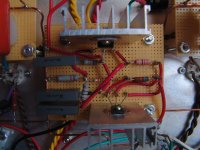
When Morgan Jones says grid-stoppers need to have their bodies right up to the grid pins, he really means that! You have at least 10mm of wire between the body and the pin. That might cause UHF oscillation.
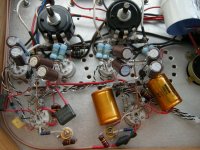
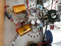
In the picture showing those Wima black box capacitors, they have long leads, and one is near the feedback capacitor. That could cause ultrasonic oscillation.
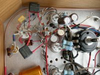
You need to think about capacitance from each and every wire to each and every other. You must avoid capacitance between input and outputs - some of your outputs are perilously close to inputs.
I mention oscillation because if you have oscillation it can beat with a transmitted frequency and any nonlinearity in an amplifier demodulates the beat frequency.
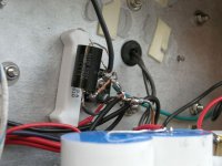
Another possibility is poor earth bonding. It looks to me as though you are using one of your input sockets as the earth bond. You can't get a really good bond with these because if you apply a decent torque they split (did that a couple of weeks ago). You want a proper M6 or 1/4" screw with serrated washers and done up really tight.
Of course, RF interference could be a common problem in your area. Do you live near a transmitter? If so, special measures might be needed.
In the picture showing those Wima black box capacitors, they have long leads, and one is near the feedback capacitor. That could cause ultrasonic oscillation.
You need to think about capacitance from each and every wire to each and every other. You must avoid capacitance between input and outputs - some of your outputs are perilously close to inputs.
I mention oscillation because if you have oscillation it can beat with a transmitted frequency and any nonlinearity in an amplifier demodulates the beat frequency.
Another possibility is poor earth bonding. It looks to me as though you are using one of your input sockets as the earth bond. You can't get a really good bond with these because if you apply a decent torque they split (did that a couple of weeks ago). You want a proper M6 or 1/4" screw with serrated washers and done up really tight.
Of course, RF interference could be a common problem in your area. Do you live near a transmitter? If so, special measures might be needed.

When Morgan Jones says grid-stoppers need to have their bodies right up to the grid pins, he really means that! You have at least 10mm of wire between the body and the pin. That might cause UHF oscillation.
I'm going to cut it short.
In the picture showing those Wima black box capacitors, they have long leads, and one is near the feedback capacitor. That could cause ultrasonic oscillation.
There supposed to be couple Jensens caps, I thought there might be leakage or something, so I changed that for experiment.
You need to think about capacitance from each and every wire to each and every other. You must avoid capacitance between input and outputs - some of your outputs are perilously close to inputs.
I thought I better re-arrange ( redo ) this part.
Another possibility is poor earth bonding. It looks to me as though you are using one of your input sockets as the earth bond. You can't get a really good bond with these because if you apply a decent torque they split (did that a couple of weeks ago). You want a proper M6 or 1/4" screw with serrated washers and done up really tight.
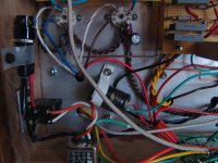
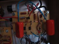
All ground goes back to Photo 4. It has been lifted with a box rectifier with 10 10w and o.o1. ( I don't know this if method is good. I did it with other amps with no problem )
I'm going to cut it short.
In the picture showing those Wima black box capacitors, they have long leads, and one is near the feedback capacitor. That could cause ultrasonic oscillation.
There supposed to be couple Jensens caps, I thought there might be leakage or something, so I changed that for experiment.
You need to think about capacitance from each and every wire to each and every other. You must avoid capacitance between input and outputs - some of your outputs are perilously close to inputs.
I thought I better re-arrange ( redo ) this part.
Another possibility is poor earth bonding. It looks to me as though you are using one of your input sockets as the earth bond. You can't get a really good bond with these because if you apply a decent torque they split (did that a couple of weeks ago). You want a proper M6 or 1/4" screw with serrated washers and done up really tight.
All ground goes back to Photo 4. It has been lifted with a box rectifier with 10 10w and o.o1. ( I don't know this if method is good. I did it with other amps with no problem )
In Photo 4, is that a power resistor? If so, it appears you're baking that capacitor. "Burn-in" is a figure of speech, not to be taken literally.
SY,
Do you mean there might be heat from the power resistor? or they might interfere each other? It is just for isolating the ground with the chassis
I did the same on the 'Red Light District' with no problem
SY,
Do you mean there might be heat from the power resistor? or they might interfere each other? It is just for isolating the ground with the chassis
I did the same on the 'Red Light District' with no problem
I just found this thread so the problem might be solved but I have found that using carbon resistors as grid stoppers is much more effective than metal film. I had a problem with a radio station in my amps. A friend recommended carbons and the radio station disappeared. The body of the resistor also has to be right up against the tube socket as has been mentioned. Good luck.
Charlie
Charlie

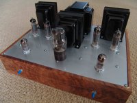
Morgan Jones Bevois Valley EL84 push-pull build
Hey all, a relative newbee here. Wanted to post info and images of my recent build of Morgan Jones Bevois Valley amp, hoping to help others out there since I got so much useful info from this site. Background: I'm about 1 year into tube audio hobby, had very little knowlege of electronics prior to this, but am a lifelong tinkerer with science background. All started with an abandoned non-functioning Lowrey organ that my son and I managed to convert into a nice 6L6 PP guitar amp. Decided to give the MJ EL84 amp a try. Followed the published schematic fairly closely, but on variation was to use a 5V4 rather than a 5AR4, 'cause I liked the looks of a 5V4 and the specs seemed close enough to be worth giving it a try. Just had to sub in a 20 uf cap before the choke in place of the 68 uf on the schematic (but did mount a 60 uf in case I want to switch later). HT was only about 5V low for the EL84s, and about 5V high out of the regulator. Used all new Edcor transformers and 10H choke, but went with 23% ultralinear taps rather than 43% (no real reason. also, did not include resistors between screen taps and screens). Used 0.2 uf coupling caps rather than 1 uf ('cause thats what I had). Cheap NOS Soviet EL84's, and E88CC's (aka 6922, 6DJ8; cyrilic label '6H23N' from Voshkod factory). MJ's description and schematic don't mention the cap/resistor bypass needed across the load resistor of the first half of the E88CC to compensate the feedback circuit and the tweaking of those and the other feedback cap/resistor. I tweaked by trial/error, ended up with ~3K and 4.7K ohms (lft channel/rt channel, respectively) + 100 pf accross the load resistor and 1k or 2.2k ohms (lft chnl/rt chnl) + 470 pf accross the feedback resistors.
Have run it about 25 hrs, sounds awesome with input direct from CD player, even on mediocre speakers. Blew a 1 amp slow-blow fuse after about 20 hrs, but after checking tubes/checking for shorts a 1.6A fuse fixed the problem....hopefully.
Biggest error: thinking that if a virtual ground is good for the 6.3V filament supply, it must be good for the 5V rectifier heater supply. Didn't work out so well at the 300V+ went to ground thru little 47R resistors. Luckily caught the problem before any damage done.
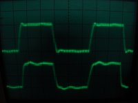
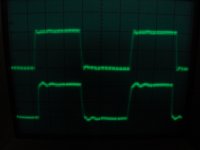
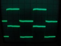
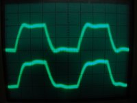
Right channel seems a bit cleaner than the left (see scope images), can't figure it out (feedback tweaking didn't improve it). Any ideas/suggestions?
Hey all, a relative newbee here. Wanted to post info and images of my recent build of Morgan Jones Bevois Valley amp, hoping to help others out there since I got so much useful info from this site. Background: I'm about 1 year into tube audio hobby, had very little knowlege of electronics prior to this, but am a lifelong tinkerer with science background. All started with an abandoned non-functioning Lowrey organ that my son and I managed to convert into a nice 6L6 PP guitar amp. Decided to give the MJ EL84 amp a try. Followed the published schematic fairly closely, but on variation was to use a 5V4 rather than a 5AR4, 'cause I liked the looks of a 5V4 and the specs seemed close enough to be worth giving it a try. Just had to sub in a 20 uf cap before the choke in place of the 68 uf on the schematic (but did mount a 60 uf in case I want to switch later). HT was only about 5V low for the EL84s, and about 5V high out of the regulator. Used all new Edcor transformers and 10H choke, but went with 23% ultralinear taps rather than 43% (no real reason. also, did not include resistors between screen taps and screens). Used 0.2 uf coupling caps rather than 1 uf ('cause thats what I had). Cheap NOS Soviet EL84's, and E88CC's (aka 6922, 6DJ8; cyrilic label '6H23N' from Voshkod factory). MJ's description and schematic don't mention the cap/resistor bypass needed across the load resistor of the first half of the E88CC to compensate the feedback circuit and the tweaking of those and the other feedback cap/resistor. I tweaked by trial/error, ended up with ~3K and 4.7K ohms (lft channel/rt channel, respectively) + 100 pf accross the load resistor and 1k or 2.2k ohms (lft chnl/rt chnl) + 470 pf accross the feedback resistors.
Have run it about 25 hrs, sounds awesome with input direct from CD player, even on mediocre speakers. Blew a 1 amp slow-blow fuse after about 20 hrs, but after checking tubes/checking for shorts a 1.6A fuse fixed the problem....hopefully.
Biggest error: thinking that if a virtual ground is good for the 6.3V filament supply, it must be good for the 5V rectifier heater supply. Didn't work out so well at the 300V+ went to ground thru little 47R resistors. Luckily caught the problem before any damage done.
Right channel seems a bit cleaner than the left (see scope images), can't figure it out (feedback tweaking didn't improve it). Any ideas/suggestions?
Attachments
-
 20 khz.JPG209.8 KB · Views: 107
 -
 10 khz.JPG207.3 KB · Views: 106
 -
 1khz.JPG11.1 KB · Views: 95
 -
 40 hz.JPG209.6 KB · Views: 196
 -
 pwr, fuse.JPG346.1 KB · Views: 490
 -
 regulator.JPG367.4 KB · Views: 503
 -
 right board.JPG324.2 KB · Views: 526
 -
 all wiring.JPG395.8 KB · Views: 566
 -
 amp.JPG298.6 KB · Views: 619
 -
 40 khz.JPG225 KB · Views: 124
You might want to zoom in on those fuzzy waveforms and see if that fuzz is an oscillation, and if not, what that noise is. Have you swapped tubes between the channels to see if the less-vs-more clean follows the tubes?
That's good advice from Sy there ivlacrosse. Looks like some type of low level oscillation or noise. Most likely a noisy tube - but it could also be a tube socket - bad solder joint - wire dressing (resulting in a signal wire being affected by stray EMF or RF signals etc,) even bad contacts on a noisy switch - pot - or signal connector.
Is the signal "fuzzy" from amp turn on or does it get worse as the amp warms up?
A few more details on the amp I posted earlier today
Thanks for the suggestions so far, I'll have to try them. Some details I forgot earlier: the scope images left to right are 40 Hz, 1k, 10k, 20k, 40khz. I have zoomed in on them a little closer and it doesn't really look like a high frequency oscillation to my untrained eye but I'll have to zoom some more (my old tektronix 60 mhz is a little fuzzy though). I think my solder joints are OK. I was pretty careful about checking them as I went. At one point I swapped out the el84s and saw no difference in the 'noisy' channel, of course I didn't think to swap the e88cc. Will try that next. I probably won't fiddle too much since the sound is very nice, unless someone thinks that amount of oscillation (if that's what it is) could be damaging.
Thanks for the suggestions so far, I'll have to try them. Some details I forgot earlier: the scope images left to right are 40 Hz, 1k, 10k, 20k, 40khz. I have zoomed in on them a little closer and it doesn't really look like a high frequency oscillation to my untrained eye but I'll have to zoom some more (my old tektronix 60 mhz is a little fuzzy though). I think my solder joints are OK. I was pretty careful about checking them as I went. At one point I swapped out the el84s and saw no difference in the 'noisy' channel, of course I didn't think to swap the e88cc. Will try that next. I probably won't fiddle too much since the sound is very nice, unless someone thinks that amount of oscillation (if that's what it is) could be damaging.
- Status
- This old topic is closed. If you want to reopen this topic, contact a moderator using the "Report Post" button.
- Home
- Amplifiers
- Tubes / Valves
- Morgan Jones's Bevois Valley amp...