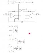
Monolitic Susy problem
Hi Jh6you,
After having GC supersymmetry for sometimes, I build your monolitic susy for comparison with the GC supersymmetry.
I got one channel working last night, there is music playing, offset stayed at 14mV after warm up. But the problem is the volume is too low even after I turn the pot to the max.
The only difference from your circuit is the output power transistor which I'm using MJ15022 and MJ15023
pair. Do you think that the low hfe of 15~60 has anything to do with this?
Also I changed the opamp rail resistor from 120ohms to 330ohms, without much difference but the my heatsink temperature rise to about 60degree. My rail voltage is +/- 15.3V. I'm using DRV134 to provide balance inputs for monolitic Susy.
Pls advise.
Regards,
Ipanema
Hi Ipanema
Nice to hear from you.
The size of 120 ohms is to control the bias current of the current boosting transistors. I tried different values and found that the 120 seems to be optimum. In my opinion, the 360 is unnecessarily too high. You already have number of 360 ohm resistors, I guess. Try 360//360 = 180 ohms and 360//360//360 = 120 ohms for your own experiment.
I found, the bigger hFE, the better result. My recent application is with the pair of MJ 15003/4 having hFE of 25-150. In addition, for more output current preparation I did paralleling two amps.
If you have any further questions, let¡¯s discuss them.
Regards
-----------
Oppositely, now I am building GC SS. For the time being on the paper ¡¦
Hi Jh6you,
Thanks for replying. Do you think that in my case the gain is too low? Should I increase the gain of the system and how? I have MJ15003,4 at hand, but would like to rectify actual problem in my system before make any changes.
What is the configuration of ouput stages? Is it class A? Most of the guys in the forum prefering higher bias possible as long as the heatsink can take it for better sound quality. Did you try it at higher bias?
Glad that you are finally going to build a GC Susy and would like to know your comments when comparing both of them.
Regards,
Ipanema
What about these Chips?
Going back to the first two pages of this thread...I ask myself if there is any reason not using those LT1210:
http://www.linear.com/pc/productDetail.do?navId=H0,C1,C1154,C1009,C1146,P1329
After all, they deliver at least 1.1A peaks. Should be OK for a headphone amp. Maybe they could even drive the Kleinhorns to amazing levels...
I suggest the name Kleinamp...."ein kleiner Amp für das Kleinhorn"
translated "a small amp for the small horn"
Cheers, Tino
As an aside, Jocko mentioned several times that he (and some others) have always been not satisfied with the sound of current feedback devices (and also amps). This could be the reason, that the LT1210 is absolutely ignored here....
Ipanema,
My MSS has relatively low gain. I guestimate as about 15dB. I used maths to get the gain figure. Since nobody gave me any second opinion, however, I am unsure that the figure is right.
SOBOZ drives my MSS. I set maximum gain of SOBOZ as lower than unity gain at its output. Still the music is too loud to go up to its max volume.
MSS is not a Class-A. Its class depends on LM6181.
The signal current of class-A amps fluctuates within the amount of bias current. Probably, this is why they do their effort to increase the bias current. But, MSS has a different concept. The voltage gain is earned from the X-ed op-amp and the necessary current is earned from the current boosters. For MSS, the bias current is nothing but the idling current just for a prepared start. In MSS case, when the output signal voltage goes up, the amount of the output signal current also goes up (to the amount preferably to be greater than the speaker requires). I believe that, by doing this, we could make the amp which has no problem with the current supply required for the ¡°low¡± impedance speakers. This could be why the transistors of higher hFE are most preferable.
In general, I do not need high gain power amp.
The thing I consider with my music system is that at loud music, still I and my guests (e.g. 4-8 persons) could talk without feeling that the music interrupts our giggling conversation in my living room. I do not mean elevator music, but with rock music, punching the kick-drum, fingering rhythm of bass guitar, crying lead guitar, screaming vocal, all on wide stage with details. Not only color of the sound¡¦
Hi Jh6you,
Do you think by increasing the resistor value of R12 and R13 and decreasing R15 will increase the overall gain? If I'm not mistaken the gain will be 2(2R12/R15) = 2(2*7.5k/1000) = 30 = 29.5dB. If I'm wrong pls show me how you arrive at the gain of 15dB?
Hmm...
I think I should change the output trans to MJ15003,4.
Thanks,
Ipanema
Do you think by increasing the resistor value of R12 and R13 and decreasing R15 will increase the overall gain? If I'm not mistaken the gain will be 2(2R12/R15) = 2(2*7.5k/1000) = 30 = 29.5dB. If I'm wrong pls show me how you arrive at the gain of 15dB?
Hmm...
I think I should change the output trans to MJ15003,4.Thanks,
Ipanema
Hi Ipanema,
You must be right.
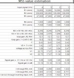
Attached my gain estimation made time ago.
The calculation did only with one side input.
Therefore, I need to double the gain, considering bothe side input, i.e. to be 30dB.
Regards
------------------
If any of you see error in calc, please comment it. Thanks.
You must be right.
Attached my gain estimation made time ago.
The calculation did only with one side input.
Therefore, I need to double the gain, considering bothe side input, i.e. to be 30dB.
Regards
------------------
If any of you see error in calc, please comment it. Thanks.
Attachments
Re: What about these Chips?
Forgot to attach.... well, nothing new, just added the LT1210 designation...
zinsula said:Going back to the first two pages of this thread...I ask myself if there is any reason not using those LT1210:
http://www.linear.com/pc/productDetail.do?navId=H0,C1,C1154,C1009,C1146,P1329
After all, they deliver at least 1.1A peaks. Should be OK for a headphone amp. Maybe they could even drive the Kleinhorns to amazing levels...
I suggest the name Kleinamp...."ein kleiner Amp für das Kleinhorn"
translated "a small amp for the small horn"
Cheers, Tino
As an aside, Jocko mentioned several times that he (and some others) have always been not satisfied with the sound of current feedback devices (and also amps). This could be the reason, that the LT1210 is absolutely ignored here....
Forgot to attach....
well, nothing new, just added the LT1210 designation...Attachments
Hi Ipanema,
I looked into the spec of MJ15022. It seems better than MJ15003 to me.
Actually, my target for the amp was 20W power for 2-8 ohm impedance speakers.
If impedance is 2 ohm, Vpeak = (2*20*2)^0.5 = 9V.
Then, required Ipeak = 4.5A --- [1].
According to the spec of LM6181, Isc = 100mA at 10V output.
So, if the output is 9V, Iload = 100x9/10=90mA from the output of op-amp through the 2 ohm impedance.
Meanwhile, at Ic of 4.5A, the hFE of MJ15003 is about 50.
Therefore, Ic = 0.09 x 50 = 4.5A -----[2].
OK, [2] is fine for the required [1].
The amp can give me 20W power for the 2-8 ohm impedance speakers.
If I see MJ15022, in the area within Ic = 5A, hFE is greater than 50. If you need higher power at low speaker impedance, I would like to recommend to use Darlington transistors.
Regards
Hi Jh6you,
Thanks for some insight into the calculation. It seems that the output limitation is set by LM6181. From the datasheet, the guranteed Isc is only at 75mA, hence I think 90mA might be a little over the edge.
Since, the base of power transistor is not driven by opamp output but by the supply modulation, I might assume that low hFE will not pose any loading problem to the opamp. Hence, I can increase the output bias as long as my heatsink and output transistor can take it. Pls advise, how high hFE can be beneficial in this circuit? I have connect the output transistor as TIP142 and TIP147 yesterday (min hFE=1000 at 5A). Hope to test it today.
Theoretically, for balance output, the output power is given as P=4Vp^2/2R = 4*9^2/2*2 = 81 watts for 2 ohms load.
For my case, 8 ohms load, P=(4*9^2)/2*8 = 20.25 watts. Thats the maximum I will get with LM6181. Ic=1.125A. Will the power increase with darlington transistor?
Regards,
Ipanema
Hi Ipanema
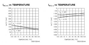
The attached sketch shows Isc curves (maximum load current) of LM6181. With 15V rail voltages, typical Isc = 130mA and limit = 100mA. The data sheet also says that typical high output drive is +/- 10V into 100 ohms. By the way, if the guaranteed figure is only 75mA, I think we again need higher hFE for low impedance load.
I agree that the base of power transistor is driven by the supply modulation. But, eventually, the supply ac current modulation is proportional to the op-amp output ac current, IMHO.
I agree with the 80W calculation for 2 ohm load and the 20 watts for 8 ohm, with respect to voltage swing. As you might already know, for the 80W for the 2 ohm load, we need peak current of Ic=9A. We understand that, if the transistor is ready for the 9A of Ic, the amp is ready for the 80W for the 2 ohm load.
I do not think that application of Darlington will incease more than 20W for the 8ohm load.
I wish your successful test with TIP142/7.
Did you do PCB-construction or p2p for your MSS?
I used p2p. I could post some pictures if you like to see.
How do you like the sound?
I am fully enjoying mine, with 10ohm/0.47uF/10ohm zobel.
I could not start building GCSS last weekend. As I informed earlier, I built three new MSS. By the way, I found a minor problem with one of them. Therefore, I spent whole week end for trouble shooting. The problem was that I soldered one point badly. Now all work okay.
Regards
Attachments
Hi Ipanema
I think R5/6 will do two roles: one for dc-return and another for stable offset. I applied these as Nelson Pass recommended. He could explain better than I do. (Where is he these days?)
With the zobel, the sound is slightly different. You could test it on your taste.
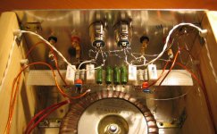
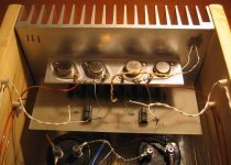
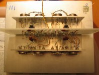
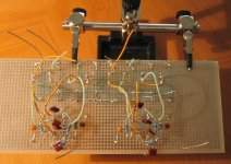
My latest MSS are also built with the breadboard and by p2p. Four pictures are as follows. The look of my soldering is bad. I however do not care the look. I just use much solder to secure the soldering points and to reduce resistance at connections.
Regards
I think R5/6 will do two roles: one for dc-return and another for stable offset. I applied these as Nelson Pass recommended. He could explain better than I do. (Where is he these days?)
With the zobel, the sound is slightly different. You could test it on your taste.
My latest MSS are also built with the breadboard and by p2p. Four pictures are as follows. The look of my soldering is bad.
I however do not care the look. I just use much solder to secure the soldering points and to reduce resistance at connections.Regards
Hi Jh6you,
Nice to look at your amplifier. I think P2P is a work of art.
I power on the TIP142/147 last night wittout R5 and R6. It heat up immediately. I measure the current at around 4A for each transistor. Funny thing is when I changes the rail resistor from 120ohms to 60ohms, the transistors is OFF. Even when I play around with other value from 60~120 ohms it always changes from OFF to overheat. Do you know what happen?
BTW, have you try any darlington configuration?
Regards,
Ipanema
- Status
- This old topic is closed. If you want to reopen this topic, contact a moderator using the "Report Post" button.
- Home
- Amplifiers
- Pass Labs
- Monolithic SuperSymmetry with Current Feedback