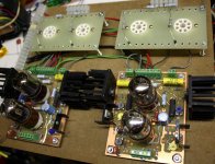
I got my PCB's today. Thanks!!
Now I've got to decide what I want to do w/ them... Right now my ideas are all over the map, from 300b to kt88 pentode mode, to big transmitting tubes. (I'm leaning towards something pentode mode w/ regulated everything in the power supply (I guess 'cause there's a lot of regulator talk on the forum at the moment))
Anyone else starting a project w/ these?
Anyone else starting a project w/ these?
Not right away, but eventually. My soldering iron has not been plugged in since October. I have been in West Virginia, or Sherri has been home, and we have been catching up on the life together that we have missed for the last few years. She is going back north tomorrow morning for a while, so it's time to start the lab up again.
First off we cleaned out a room in the house and converted it to storage. I will be cleaning out our rental warehouse to save the $2500 a year in rent. The room has only about 1/3 the space, so a lot of stuff will get sold, given away or trashed. I need to catch up on some Tubelab stuff, fix the stale web site and build new versions of my boards to update the parts lists, then...
There are two nearly finished guitar amps that last saw power in November, and about 8 to 10 finished PC board designs that are still in my computer, drawn up in my down time over the last year. There are a couple more guitar amps, several driver boards, two power supplies, and another amp. None have been built, so they all will go through some revisions, and some will be abandoned.
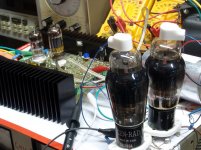
Once a driver board or two are built and working, then I will get them, along with the two I already have working, and a pair of Petes new ones together with this breadboard (I have turret boards for Octal, Compactron, and 9 pin miniature output tubes) for some serious testing. I still have a pair of 400 Watt OPT's that need something to keep them warm!
Output tubes.....everything from litttle runts, to KT88's to 45's, 300B's, and 307A's (shown with another of my driver boards) to sweep tubes...lots of sweep tubes, and UH these..... (6146a in the rectifier socket for size comparison)
Attachments
Will publish a list of parts and specifications of transformers ?
I'm not sure who you were asking, but I am sure that there will be some amps built using these boards and they will be documented here. Unlike the red board thread the possibilities for boards like these are endless. The red board had the power supply and the output tubes on board. These boards are just the drivers, everything else goes off board, or on additional boards. The output tubes can be just about anything with reasonable drive requirements.
Pete has already done a KT88 amp, it's on his web site. I may test some KT88's but I doubt i'll do a KT88 amp since I already have one. I plan on doing the unusual stuff and at least one BIG sweep tube amp, and yes they will be documented.
I will certainly document and post what I end up doing, but I am learning as I go so it will likely be a couple of months before I have any useful info up.
Pete said he's busy for a while.. Same w/ Tubelab.
George, I can't wait to get one of your universal drivers.. Or even just a schematic (Maybe I just need to look around for that.)
These driver boards definitely make for a fun project! It's great to have some of the pieces in place, like a road map. But you're still free to take it in any direction you want to go.
George, I can't wait to get one of your universal drivers.. Or even just a schematic
The driver board shown in the breadboard in the first picture above was developed in this thread. The schematic is in post #460.
http://www.diyaudio.com/forums/tubes-valves/133034-6l6gc-ab2-amp.html?highlight=6l6gc+ab2
The breadboard is essentially this schematic except for the power supplies. Chris and I did a collaborative effort on the driver design with me building these boards and his being PTP wired. I used bench supplies so I could experiment with a wide variety of tubes. The power supplies shown are his design and specific to 6L6 type tubes, although others will work.
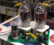
The driver board shown in the second picture uses the same schematic but uses 9 pin miniature tubes. In both cases the second tube is a 6SN7 or a 6CG7/6FQ7 which is a 9 pin 6SN7. The first stage can be one of several different tubes by changing the plate load resistors. The resistor values depend on the tube type, B+ voltage and how much drive voltage you need. The values shown on Chris's schematic are for 6SN7's or 6CG7's in both places and about 400 volts of B+. As shown it puts out enough drive to crank KT88's in triode into clipping with 450 volts of B+.
I have also designed several flavors of driver boards that use the same basic schematic except that a pentode LTP is used for the second stage. The pentode can be set up for higher gain and a larger voltage swing, which I need for some of my experiments. There are several versions of PCB's that all use a similar schematic. None have been built yet. A turret board was assembled to verify the concept about a year and a half ago. It has not seen power since then.
There are two that use 3 octal tubes, a 6SN7 and two 6SJ7 or 6AG7, and another that uses a 6SN7 and two 6K6 or 6V6.
There is one that uses a 12A*7 and two 6EJ7's. Another with two tubes that each contain a triode and a pentode.
There is a PCB for the 6AU6 - 6AQ5 version all pentode amp that I built several years ago....I found the prototype while throwing stuff out. I think it could make a good little amp or a mid sized driver driver.
There are a few more that I can't remember now, mostly based on tubes that I have lots of.
Hi George.
I refer to a basic parts list to start , for example C5 , C9 , R10 and R27 have no value , all other parts if they are and it seems a good point to start for KT88.
It can be assumed that all resistors are 0.5 W unless otherwise indicated?
The XPWR002 of EDCOR would work?
5K is the best impedance for KT88?
Thanks.
I haven't had the time to study the parts list, but it looks like I will real soon. I am preparing for a 500 mile road trip tomorrow morning. If the hotel has fixed the internet I'll have more info tomorrow night, if not I'll be back Sunday afternoon.
I am going to the Orlando Hamfest with a stop at ESRC to stand in awe of 4MILLION vacuum tubes.
Home
Vacuum Tubes - Audio Tubes - ESRC Vacuum Tubes - Electron Tubes
I am going to the Orlando Hamfest with a stop at ESRC to stand in awe of 4MILLION vacuum tubes.
Home
Vacuum Tubes - Audio Tubes - ESRC Vacuum Tubes - Electron Tubes
George, I like that 6l6 amp! Now I've got another long thread to read. What do you do when you've built far too many amps ") ?
?
About using a pentode LTP on one of your boards, that's what I was thinking about doing w/ this. Attaching your power drive circuit after Pete's PCB, to some gm70's that have been sitting in a drawer for years.. and a couple of transformers collecting rust in my basement...... But.. It's a totally crazy idea as I have no need for that power.
First up is playing w/ some smaller pentodes (same ones as your 2nd pic above). regulate the screens & bias, shunt/schade feedback.
?I have also designed several flavors of driver boards that use the same basic schematic except that a pentode LTP is used for the second stage.
About using a pentode LTP on one of your boards, that's what I was thinking about doing w/ this. Attaching your power drive circuit after Pete's PCB, to some gm70's that have been sitting in a drawer for years.. and a couple of transformers collecting rust in my basement...... But.. It's a totally crazy idea as I have no need for that power.
First up is playing w/ some smaller pentodes (same ones as your 2nd pic above). regulate the screens & bias, shunt/schade feedback.
Hi George.
I refer to a basic parts list to start , for example C5 , C9 , R10 and R27 have no value , all other parts if they are and it seems a good point to start for KT88.
It can be assumed that all resistors are 0.5 W unless otherwise indicated?
The XPWR002 of EDCOR would work?
5K is the best impedance for KT88?
Thanks.
Be aware that this board is not really a "turn key" design, like some of my other boards are. It can be built many ways, and is really targeted at advanced builders.
You could build the same amp that I will, but I think most people who use these boards will be doing their own thing with them.
The values shown on the schematic are what I built as a breadboard / prototype - missing values = component that was not used.
When I get the time, I will post some additional info on what I wind up actually building as a completed amp (I'm pretty sure it will be triode-connected KT88's as shown on the website now) including a detailed parts list. I'm also more than happy to post info on my website about designs that others come up with using this board.
Pete
I left work today with a list of things I needed to do.........but there were two shiney red things in my mail box. I put them aside and decided to do some of the stuff on my list......well that lasted about 5 minutes.
I have been stuffing parts into the boards. They are only about 1/3 done, and I really have other stuff to do tomorrow, but I found a small mistake in the documentation.
R5 and R6 are switched on either the PC board or the schematic. The two don't match. On the PC board R6 is the stopper and R5 goes to ground. The schematic shows R5 as the stopper and R6 going to ground. Put the carbon comp stopper in the R6 holes, it connects directly to pin 2 of VT1.
I haven't seen a parts list, so I don't know what it says. I am making mine up as I go along based on what parts I have here. I am also building mine "upside down" like my first red board. It makes it easier to work on when live, and easier to change parts without flipping the board over. I expect these things to go through lots of changes before they are no longer useful.
My first red board still works, and my boss has the second one so that he can copy off of it to build his own. After determining that an SSE won't drive Maggies, there was only one real choice and it was red, and set up for 125 WPC.
I'm having a hard time figuring out how much current the LTP can deliver. I have more reading to do...
But my question of the day.. Can I set up this board for A2 operation? Positive bias.
I'm thinking of trying some small transmitting triodes... I was just at the local electronics surplus store and they have some 35t's in their tube bins.
I've finally gotten a pretty good grasp on simple single ended class A, but this is the first I've even thought of A2... and PP on top of that (pentode ltp on top of that).
I guess I'm looking for a simple "yes" or "no"... Or "yes but you'd need to add another stage" (I'd do mosfet follower) to be sure i'm looking in the correct direction. Then I'll continue my research...
thanks!
I'm having a hard time figuring out how much current the LTP can deliver.
Even if the LTP could deliver a few watts (stay tuned to this channel) it wouldn't help drive the output tube grids into AB2. The issue isn't the LTP, it's the coupling caps.
The grid of an output tube in AB1 looks like an infinite resistance in parallel with a amall capacitance. There is a grid resistor to ground or the bias supply. The driver must only drive the parallel combination of the grid capacitance and the bias resistor.
As soon as the boundary into AB2 is crossed the grid becomes a forward biased vacuum tube diode to the cathode. Like any forward biased diode it is a low impedance, the harder you push it into conduction, the lower the impedance goes.
Lets assume that the driver can source and sink infinite current. As long as we stay in AB1 the outout tube's grid will follow the driver plate faithfully. When the grid enters AB2 it's impedance drops. This changes the time constant of the coupling cap / driver impedance network. When testing with a sine wave the charge / discharge cycle is symmetrical so nothing unusual is noticed. I have observed the old red board pushing the grids up to about +25 volts on sine waves.
When you play music the charge / discharge cycle is not symmetrical. This and the shifting time constant will guarantee that the bias on the output tube will shift all over the place and the recovery time can be long (seconds) if the amp is overloaded.
If AB2 is contemplated the grid of the output tube must be driven directly by a low impedance source. Traditionally there have been two ways of doing this.
A driver transformer with a low DC resistance can be used to deliver the bias voltage to the grid, and some audio power can be applied to the transformer primary to overcome the low impedance grid.
A cathode folllower can be used to deliver the grid current and its cathode resistor will deliver the bias voltage. This works but cathode followers are not perfect. The factor limiting a cathode follower is the Gm of the active device......That's why I use mosfets.
There are some advanced vacuum tube circuits that work quite well at driving AB2 outputs. Search this forum for "Augmented Cathode Follower".
Even if the LTP could deliver a few watts (stay tuned to this channel) it wouldn't help drive the output tube grids into AB2. The issue isn't the LTP, it's the coupling caps.
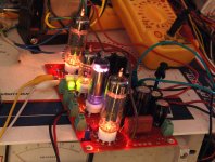
I stuffed most of the parts into a board. I didn't follow any parts list, I just sat down with a board and a printed schematic and made it up as I went along. What can you drive with this board??????
Well I decided to try something that Pete probably never dreamed of. I decided to drive........an output transformer. As I said above the coupling caps are the issue with drive power, so I wired an OPT right up to the plates of the pentodes, plugged in some healthy tubes, cranked the current up to the melting point of the 10M45 (R17 = 0 ohms), and cranked the signal generator up until the distortion meter read 5%. The results......7.5 watts with a 13K ohm load and 320 volts of B+. Yes, the little driver board can deliver 7+ watts, and this is limited by the CCS current. Plug in an LM317 and more watts will flow. The THD was 0.34% at 1 watt, maybe I'll hook some speakers to it.
As time permits I will hook this thing up to some big power tubes but next up is a bunch of little guys that I need to make a decision on soon.
Attachments
That's awesome!
I"m getting hooked on this little transmitting tube idea. I read everything I could find on A2 operation last night. I'm also thinking parallel tubes.. There will be a lot of off-pcb stuff going on (the mosfet followers and bias for each tube). It's completely illogical, but those bright little eimac tubes are pulling me down that path.
Well, my goal for today is to order a bunch of components so I can start building the driver boards..
Hey,
I'm wanting to play around w/ loadlines for these tubes.. The Tubecad/ampcad software doesn't have 35t's or 3c24's in it, does it? I'd definitely be willing to purchase it, if so.
Since these tubes aren't really audio tubes, the info online about them from people who have built amps, is all over the map.. (200v to 1000v.... 2.5ktx to 12ktx, etc)
The Tubecad/ampcad software doesn't have 35t's or 3c24's in it, does it?
My version is several years old, but it is limited to triodes and triode wired pentodes only. It only lists the common audio tubes but did have the 845 and 211. The results pretty well matched the 845 amp that I made.
If you look at the tube data sheets for the tubes you specify the required plate to plate load impedance gets pretty high as you increase the plate voltage. OPT's that are much above 10K ohms get real hard to make with a HiFi type frequency response. The usual solution is paralleled tubes at a lower voltage, but tube matching becomes an issue. If you go this route you need a way to set the bias individually for each tube. That means a seperate mosfet driver for each tube.
I was tinkering with transmitting tubes for a while, and yes they light up the room quite well, but far more power for far less effort and expense can be had with sweep tubes. A pair of 833A's per channel would be cool though.
High impedance triodes like the 35t, 3C24, 100th can be used with local (Schade) feedback to the driver plate, just like a pentode, and it will result in low plate resistance so you can use a low impedance (~5K) output transformer. The feedback goes to the driver plate before the follower to keep the grid current out of the feedback circuit.
The thing that makes local plate-plate feedback work well is a relatively high impedance driver and an output stage with fairly high voltage gain.
That's awesome!
I"m getting hooked on this little transmitting tube idea. I read everything I could find on A2 operation last night. I'm also thinking parallel tubes.. There will be a lot of off-pcb stuff going on (the mosfet followers and bias for each tube). It's completely illogical, but those bright little eimac tubes are pulling me down that path.
Well, my goal for today is to order a bunch of components so I can start building the driver boards..
Hey,
I'm wanting to play around w/ loadlines for these tubes.. The Tubecad/ampcad software doesn't have 35t's or 3c24's in it, does it? I'd definitely be willing to purchase it, if so.
Since these tubes aren't really audio tubes, the info online about them from people who have built amps, is all over the map.. (200v to 1000v.... 2.5ktx to 12ktx, etc)
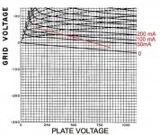
I've been looking at the 35tg myself and although efficiency is super low< it would be fun to try. A small SE should be easy to create. Looking at the constant plate current curves is a little disorienting but the load line construction process is the same. Here are the tradeoffs for a small SE:
Idle plate dissipation should be 40 watts or so to keep the plate in the dull orange range.

The 35tg gm is listed at 2850 but that's at 2000V. If it's even 2000, that gives a Schade plate resistance of something like 500 ohms with 100% feedback. A 5K OPT is a nice candidate as the end damping factor may be in the range of 5-6.
Looking at the low-swing end of the curves with 5K in mind suggests somewhere in the region of 150mA peak plate current, 150V min Vp, which needs about 75mA grid current (third dotted line up). That's 225 mA cathode current.
So I could use ~500V * 80mA as the quiescent point and swing +/- 70 mA into 5K, giving about 250VRMS for up to 12.5W output power. In reality it's about a 10 watt amp.
Class A push-pull could also be interesting and get a little more ambitious to the 25-30 watt range for 2 tubes.
Class AB push-pull with these is quite ambitious and usually ends up in the KV B+ space for an optimum design.
Attachments
Last edited:
- Status
- This old topic is closed. If you want to reopen this topic, contact a moderator using the "Report Post" button.
- Home
- Amplifiers
- Tubes / Valves
- Mono push-pull driver PCB