The differential amp is similar to the long-tailed pair, almost the same.
The Long-Tail Pair
It was used in the well-known Williamson amplifier between the phase splitter and output tubes (google williamson schematic). I am having trouble pointing you to a specific site or reference for more detail. Think of the interaction between the two tubes due to sharing a common cathode resistor. Apparently it creates good balance between the the two output signals. I'm a newb, can't help any more than that sorry.
Don't apologise, you're already helping by pointing me to the right direction ")
That does make sense, but one thing that confuses me a bit on the circuit from your previous post is why is there two differential amplifier stages? Yesterday I found a link (can't find the source now :/) with a similar setup and it said that the first stage does the amplification and the second is responsible for removing the common-mode noise. But why isn't one stage enough?
Thanks for your help!
Nuno
Think of the interaction between the two tubes due to sharing a common cathode resistor. Apparently it creates good balance between the the two output signals.
That does make sense, but one thing that confuses me a bit on the circuit from your previous post is why is there two differential amplifier stages? Yesterday I found a link (can't find the source now :/) with a similar setup and it said that the first stage does the amplification and the second is responsible for removing the common-mode noise. But why isn't one stage enough?
Thanks for your help!
Nuno
No, look, I did not mean to use a phase splitter, since your signal is already split. Just to use yet another valve stage before the power tubes, i.e. two independent triodes (found in one ECC81 for example). The idea is that since you already have the high voltage, it is not complicated.
Either that or you can use a Schmitt stage, with the two inputs driven by your two signals. It all depends on how much gain you need there. For simplicity, go with the independent stages.
Either that or you can use a Schmitt stage, with the two inputs driven by your two signals. It all depends on how much gain you need there. For simplicity, go with the independent stages.
No, look, I did not mean to use a phase splitter, since your signal is already split.
I got that from your first post. The op-amp I initially implemented was just amplifying and removing the common-mode noise but still used the split signals (it was not a phase splitter). I accept that using tubes might be a better solution...
Just to use yet another valve stage before the power tubes, i.e. two independent triodes (found in one ECC81 for example). The idea is that since you already have the high voltage, it is not complicated.
Ok, this is when my knowledge for tube circuits becomes a bit limited. As far as I understand, the setup you're suggesting will just amplify the two signals from the balanced XLR. How is that going to help me removing common-mode noise or am I missing something here?
Either that or you can use a Schmitt stage, with the two inputs driven by your two signals. It all depends on how much gain you need there. For simplicity, go with the independent stages.
I've uploaded a new version of the circuit where I've substituted the op-amp for what I think is what you mean with Schmitt stage (based on the long-tail pair article that Ian444 provided). Is that the sort of thing I should be heading to?
Thanks for your time
Nuno
Attachments
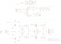
Common noise is rejected because you already have an XLR connection. With the schmitt , you also reject power supply noise. I just mentioned the simple approach because the better is the enemy of the built! Ian is right, you do not necessarily need a transformer in the input, except if you predict you need galvanic isolation from the input.
Thank you both for the comments and image.
Ideally, I wouldn't want to use the transformer at the input as it will affect the frequency response and it will cost me ~£45 :/ but I think I might use it just for insurance, as I'm not sure about the current ratings of the Line 6 HD500 and I don't want to overload the equipment...
Ideally, I wouldn't want to use the transformer at the input as it will affect the frequency response and it will cost me ~£45 :/ but I think I might use it just for insurance, as I'm not sure about the current ratings of the Line 6 HD500 and I don't want to overload the equipment...
Ian444's schematic looks like a great way to go. My concern, being that it's a guitar (power) amp, would be whether that setup can drive the el84s into clipping while also having decent output wattage. I would want the option of overdriving the outputs. So I’d be looking to maximize the gain in the drivers and trying to determine if their outputs would push the el84 grids to a peak voltage more than the predicted bias. May be good to increase the screen resistors above 820, under this approach, from what I've read.
Line 6 now also has complete amps that use tube outputs but I haven’t heard any yet. A friend uses his line 6 into his 1951 Ampeg Mercury accordion amp. He keeps the volume control on the amp pretty low and it works great for that.
Speaking of volume control, I would want one on the power amp. A “crossline” or “Larmar” before the stoppers, or a dual pot on the grids of the drivers are options. If there’s no volume control, I’d need a standby switch in case you want to plug in or unplug while it’s on. I guess they have “shorting” XLR sockets for the input to avoid noise when nothing is plugged in.
jjman,
My guess is the Line6 pre is going to provide sufficient sound profile without relying on the amp for very much of the distortion. Having the tube amp, even with a relatively clean set-up, will give the preamp some added 'balls' and warmth it needs.
The Line6 pre's that I have heard, sound pretty great all by themselves. It's worth building it to try it.
..Todd
- Status
- This old topic is closed. If you want to reopen this topic, contact a moderator using the "Report Post" button.
- Home
- Amplifiers
- Tubes / Valves
- Mono 5W-17W Power Amp using EL84 push-pull