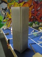
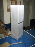
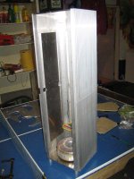
Mono 160W (16Ohm) Aleph-X towers
One Tower:
1*800VA 2x30V toroid (I'll buy a second one when I have enough money)
CLC filtering
2-3mH air core chokes (still have to wind them from pairs 1mm wire)
4x 37000uF
4 (maybe 6)x 68000uF
16 output devices
Outer dimensions:
250mm x 250mm x 820mm
front
One Tower:
1*800VA 2x30V toroid (I'll buy a second one when I have enough money)
CLC filtering
2-3mH air core chokes (still have to wind them from pairs 1mm wire)
4x 37000uF
4 (maybe 6)x 68000uF
16 output devices
Outer dimensions:
250mm x 250mm x 820mm
front
Attachments
Whooohoooo, you intend to ride the A-X at 1,4*30 volts? 42 volts?? You better check Wuffwaff's excell page1*800VA 2x30V toroid

Steen

One comment from a mechanical engineer, if I may.
You would find that long and narrow heatsinks are not effective for natural convection. The fins are too long and hence resistance to air flow too high. This is why power amplifier heatsinks tends to be wide and short. After 150mm length, the thermal impedance of almost all heatsinks levels off (i.e. no further gain for any additional length). Increasing the spacing between fins helps, but then you loose area in turn given the same width.
Of course this is not the case if you use force convection -- i.e. fan.
Patrick
wuffwaff said:Hi,
2x30V really is a bit too much. 2x18V primaries will give you 200 watts in 16 ohms so even if the bias isn´t that high you will be wasting quite a lot of power.........
William
Are you sure?
2x18v secondaries gives 50V rail to rail. With some power-supply and mosfet losses this leaves about 45V. 45^2/16=127W
Still 30V is probable a little too high. Maybe I should consider LCLC or LCRC power supply filtering. or buy a new pair of toroids.
EUVL said:One comment from a mechanical engineer, if I may.
You would find that long and narrow heatsinks are not effective for natural convection. The fins are too long and hence resistance to air flow too high. This is why power amplifier heatsinks tends to be wide and short. After 150mm length, the thermal impedance of almost all heatsinks levels off (i.e. no further gain for any additional length). Increasing the spacing between fins helps, but then you loose area in turn given the same width.
Of course this is not the case if you use force convection -- i.e. fan.
Patrick
Could you elaborates on this with some calculations?
Wes Marquenie said:2x18v secondaries gives 50V from rail to rail. With some power-supply and mosfet losses this leaves about 45V. 45^2/16=127W
Remember, by the nature of its topology, the AX is bridged!
pinkmouse said:
Remember, by the nature of its topology, the AX is bridged!
So....
The rail-to-rail voltage is the limiting factor for the voltage (and current/power) over the load.
pinkmouse said:Bridged amps are differential, so with your 50V rails, the speaker will see 100V at max output.
I was talking about rail-to-rail. NOT rail-to-gnd.

> Could you elaborates on this with some calculations?
You need a full 3D thermal simulation to be accurate on this, and it also depends on boundary conditions such as temperature difference. The smaller the temperature difference, the less efficient is the heatsink.
Go to the website for Fischer Electronics and find a heatsink profile similar to yours. You will see a curve for thermal resistance vs. profile length. And 99% they flatens at around 150mm length. So you never see a curve much beyond 200mm.
And bear in mind that these quoted resistance values are based on a heatsink temperature of 50 to 70 degC ABOVE ambient. Check the definitions.
Patrick
EUVL said:> Could you elaborates on this with some calculations?
You need a full 3D thermal simulation to be accurate on this, and it also depends on boundary conditions such as temperature difference. The smaller the temperature difference, the less efficient is the heatsink.
Go to the website for Fischer Electronics and find a heatsink profile similar to yours. You will see a curve for thermal resistance vs. profile length. And 99% they flatens at around 150mm length. So you never see a curve much beyond 200mm.
And bear in mind that these quoted resistance values are based on a heatsink temperature of 50 to 70 degC ABOVE ambient. Check the definitions.
Patrick
I have looked at the Fischer website and found a similar heatsink profile (SK 166). All graphs stop at 200mm so there is not much to say beyond that point unless K/W flattens much before that point. One thing I noticed was that it started to flattens earlier when the fins are deeper.
I found a java based heatsink calculator which seems to correspondent with the fischer measurements. Wider heatsinks are more efficient then higher heatsinks. In my case using the calculator wide is about 27% more efficient than high.
However my floorspace is limited and if they were huge and flat I would probably put them on top of eachother.
If you're wondering why the heat dissipation flattens out when the heat sink gets too tall, I believe it's because the effect buoyancy has on the air decreases. That's why fins should be vertical in passive applications like this, otherwise you don't get the hot air rising (think of it as very slow active cooling). When the heatsink becomes really long, you begin to lose efficiency due to the lack of increasing temperature difference along the length of the fin.
I hope I explained that half decently...I'm not an engineer, just one in training
A heat transfer textbook from the library will give the equations you need. Patrick is right though, simulation software is easiest. There's plugins for Matlab that can do this.
I hope I explained that half decently...I'm not an engineer, just one in training
A heat transfer textbook from the library will give the equations you need. Patrick is right though, simulation software is easiest. There's plugins for Matlab that can do this.
> However my floorspace is limited and if they were huge and flat I would probably put them on top of each other.
Then the top one gets hotter than the bottom. Warm air goes up.
For limited floor space, best solution is fan (a slow moving, large diameter one for low wind noise), or better still water cooling. Compared to electricity, water is cheap.
Can't cheat physics, unfortunately.
Patrick
Then the top one gets hotter than the bottom. Warm air goes up.
For limited floor space, best solution is fan (a slow moving, large diameter one for low wind noise), or better still water cooling. Compared to electricity, water is cheap.
Can't cheat physics, unfortunately.
Patrick
Wes Marquenie said:
Are you sure?
2x18v secondaries gives 50V rail to rail. With some power-supply and mosfet losses this leaves about 45V. 45^2/16=127W
Still 30V is probable a little too high. Maybe I should consider LCLC or LCRC power supply filtering. or buy a new pair of toroids.


shame on me! You´re right of course. Probably too much alcolhol yesterday evening.......
William
wuffwaff said:alcolhol
What ?
For such a large heatsink heat has to travel a long way.
If you talk metric, heat conductivity of Aluminium is 235 W/M*K.
If temperature of one end is 1 degree lower, heat will travel from one side to the other through a cubic block with 1 meter sides at a rate of 235 joules per second.
A normal amplifier heatsink does not have a 1 square meter cross section, 0.005 m2 is already a generous size.
At 1 degree difference the heat conductivity of aluminium would only allow 1 watt to travel from one side to the other.
Together with the effect of decreasing temperature difference between heatsink and the air layer to the sink heat transfer efficiency would reduce to zero.
For a lot of heatsinks, the heat curve in the range between 50 and 200 mm has an almost quadratic behavior.
A 200 mm heatsink does not have a thermal number which is half of the one of a 100 mm heatsink, more like square root 2=>0.7
see some heat transfer curves at www.fischerelektronik.de
- Status
- This old topic is closed. If you want to reopen this topic, contact a moderator using the "Report Post" button.
- Home
- Amplifiers
- Pass Labs
- Mono 160W Aleph-X towers