> here you will find some more photos from my F5X and of course some listening impressions.
I think you meant this page :
http://www.diyaudio.com/forums/pass-labs/121228-f5-power-amplifier-114.html#post1973964
Patrick
I think you meant this page :
http://www.diyaudio.com/forums/pass-labs/121228-f5-power-amplifier-114.html#post1973964
Patrick
Hi Thanh,
here is the actual schematic.
Regards, Uwe
Thanks for the schematic.
Have you also tried it with bipolars on the output?
Chef seemed to think it sounded better (better than irf610/9610).
1st try was CheffDeGaar's version, second try was the version with IRF-MOSFETs. Here is a link to some posts regarding my version with IRFs:
http://www.diyaudio.com/forums/pass-labs/143128-ugs-problem-3.html#post1950135
IMHO, the actual version sounds better then the second and the first try (maybe due to the low open loop gain and the low harmonic distortions compared to the others). Otherwise I would use one of the previous versions.
Drawback: the MOSFET-based versions have a poorer DC offset stability.
Uwe
Just had a look at the square wave tests.
The lines look a little thick at top and bottom of the square wave. Is it oscillating?
The top and bottom line is also thick for the input voltage (the yellow top trace). Maybe the signal generator is oscillating ;-)
No, I assume this is some kind of quantization noise from the scope.
Just looking at the irf version schematic. It seems you don't have any gate resistors.
I didn't read the whole thread so appologies if I am stating the obvious.
Forget this schematics, I used them only for simulations. Of course I use gate stoppers on the real pcbs.
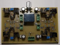
Here is a picture of the UGS with IRFs. Unlike the UGS with Toshibas this version has only single ended inputs (the inverted input is shorted to GND on board) and an additional Alps pot for volume control (at the output). It's still working.
Attachments
Hi Thanh,
here is the actual schematic.
Regards, Uwe
oh thanks smyslow,
")
thats a real gift and worth a try!
regards Gerd
- Status
- This old topic is closed. If you want to reopen this topic, contact a moderator using the "Report Post" button.
- Home
- Amplifiers
- Pass Labs
- Modified Dual Differential F5