Hello electonic experts,
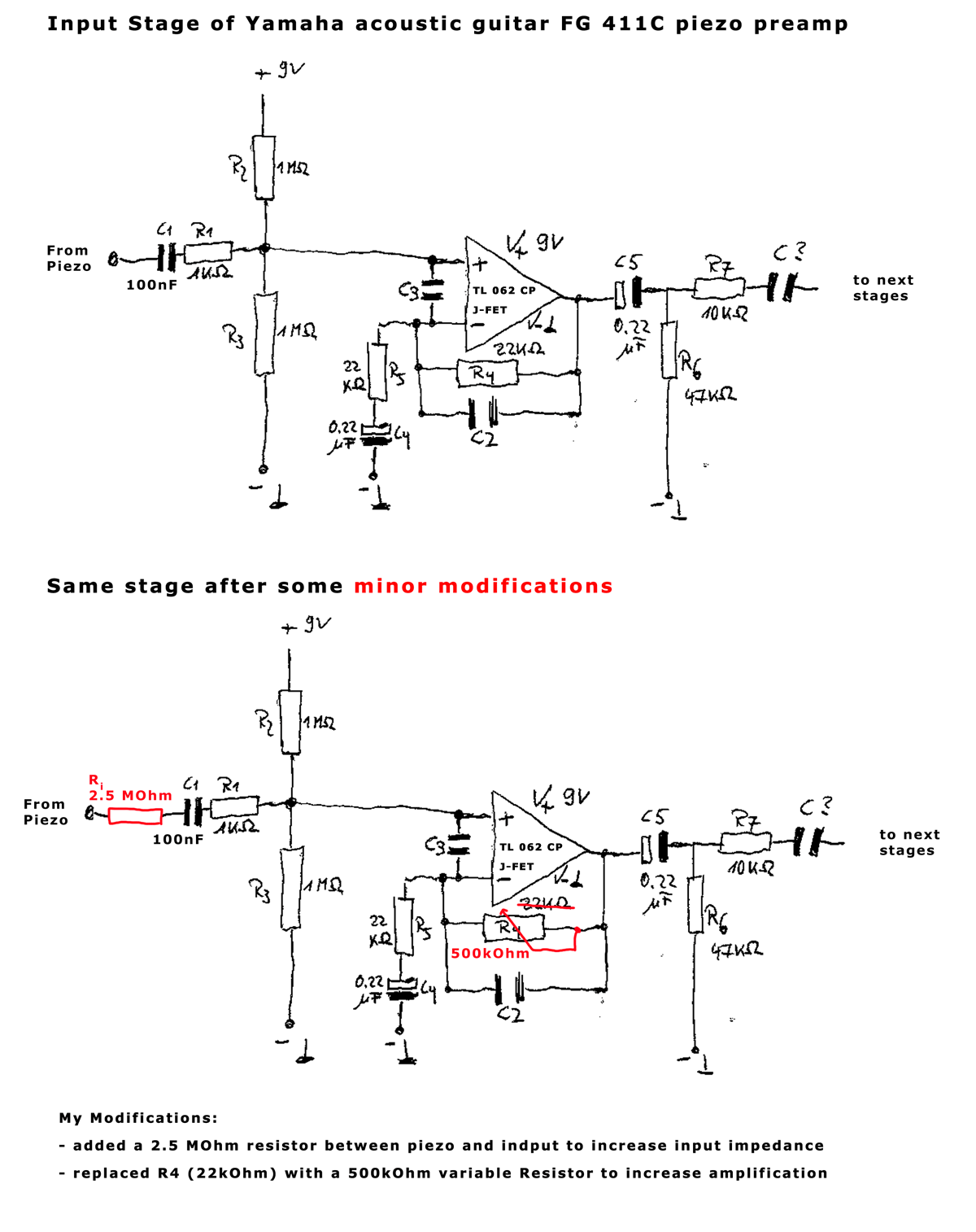
I recently exchanged the original piezo of my old Yamaha FG 411C with a standard fishman acoustic matrix piezo. Since the fishman has way lower output I'm trying now to modify the built in preamp of my guitar to go along with the fishman (see partial circuit diagram below).
There are two main questions at this time:
1. when I'm raising the value of R4, the amplification doesn't react like I thought it should. Amplification should be something like R4/R5, but when I'm setting R4 to 100kOhm I don't get much more loudness than when I'm setting it to 50kOhm. Raising amplification by raising R4 doesn't seem to be linear at all. Can you tell me why?
2. I added the Ri resistor to the input to raise input impedance. Modern piezos should be connected to preamps with 2-3 MOhm input impedance, so I thought this might be the easiest way to get this done. Other aproach would have been to raise R2 and R3 to about 3MOhm (or more) each. Would this have been the better approach? Why?
Hope someone out there can give me some hints.
Yours
Rob
The value of C2 could be a determining factor in the gain calculations. Depends how large it is.
Ri probably isn't a great idea as it also forms an attenuator with the combined parallel resistance of R2 and R3 (500k).
A J-FET input opamp like the TLO62 will allow you to raise R2 and R3 if needed. 10meg is no problem.
Ri probably isn't a great idea as it also forms an attenuator with the combined parallel resistance of R2 and R3 (500k).
A J-FET input opamp like the TLO62 will allow you to raise R2 and R3 if needed. 10meg is no problem.
Hello Mooly,
thanks a lot for your informations so far.
C2 is a brown ceramic disc with the inscription "151K". I can't figure out the value.
Further measuring of input vs output signal voltage has shown that Ri actually wasn't a good idea, seems to take away much of the signal. That's why I had the idea of replacing R2 and R3 with way bigger values to get a higher input impedance. I figure that I have to count the impedance of the 9V block battery into the calculation, so if I'm replacing R2 and R3 with 3MOhm values, what overall input impedance will I get?
Yours
Rob
Last edited:
151 is 150pf, it is one, five and one zero, so 150.
The 9 volt battery will have a low impedance (and will probably have a decoupling cap across it as well) and so that means the +9 volt rail and the 0v side are effectively the same point as far as audio frequencies go.
Replacing R2 and R3 with 3meg resistors would give an overall input impedance of 1.5meg. Because the two values are always equal we can just divide one of them by two to get the result.
Hello Moody,
thank you so much again! I will try that approach then, sounds way better than the Ri resistor. And when I won't be losing so much signal to the Ri resistor, maybe the variable R4 resistor will be sufficient to get the needed amplification.
Does the 150pF C2 capacitor have any big effect?
Yours
Rob
thank you so much again! I will try that approach then, sounds way better than the Ri resistor. And when I won't be losing so much signal to the Ri resistor, maybe the variable R4 resistor will be sufficient to get the needed amplification.
Does the 150pF C2 capacitor have any big effect?
Yours
Rob
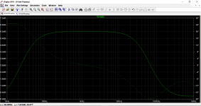
The 150 pf will have a big effect but only at frequencies over about 10kHz from which point the gain will roll off. That's on the version with a 22k feedback resistor.
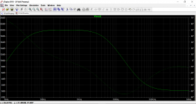
If you alter the feedback resistor then the cap interaction will change, make the feedback 200k and the roll off starts much earlier at around 1kHz.
If you alter the feedback resistor then the cap interaction will change, make the feedback 200k and the roll off starts much earlier at around 1kHz.
Hello Mooly,
thanks for the simulations! I think I'll start with replacing R2 and R3 with 3.3MOhm resistors and then I'll play with the R4 value until I get a satisfying amplification. When I have found out a good value for R4 I'd love to ask you for one more frequency range simulation with that value and maybe for a suggestion to move the roll off point higher up.
Until then thank you again for your very much appreciated help.
Yours
Rob
Hello Mooly,
after replacing R2 and R3 with 3.3MOhm resistors and removing Ri I did some more measuring.
Applying a signal of 400Hz and 200mV to the Input of the circuit, I measured the output signal of the OpAmp and of the whole preamp while changing the value of R4.
These are my Results:
Input Signal AC 400Hz 200mV
R4 R4 / R5 Output OpAmp Output Preamp 22k 1 0.4V 35.8mV 50k 2.27 0.67V 59.1mV 130k 5.90 1.41V 126mV 250k 11.36 2.38V 216mV 500k 22.72 3.07V 279mV
As you can see, the signal output of the opamp (and the whole preamp) isn't linear to the change of R4. The higher R4 gets, the less gain in amplification I get.
From earlier experiments with a cheap artec preamp which went quite ok with my fishman piezo, I know that I should get an overall amplification of 1.5 from the whole preamp. When I fed 200mV signal into the Artec preamp, I got 300mV output. So that's about what I should achieve with the modified Yamaha preamp too.
Do you have any suggestions how to achieve this amplification?
Yours
Rob
Unfortunately it can´t stand a 9V battery 
Also indicate units for each number mentioned.
Thanks.
Recommended operating voltage up to 5.5V ; Absolute maximum 7V .
PLEASE repost in a readable form, as a table or at least separating values line by line, as-is it´s a riddle.R4 R4 / R5 Output OpAmp Output Preamp 22k 1 0.4V 35.8mV 50k 2.27 0.67V 59.1mV 130k 5.90 1.41V 126mV 250k 11.36 2.38V 216mV 500k 22.72 3.07V 279mV
Also indicate units for each number mentioned.
Thanks.
You don't NEED no stinking 9 volts! Two 'AA' batteries will give you a ~1.4 volt peak signal (enough) and last a LOT longer than a 9-volter.Unfortunately it can´t stand a 9V battery
Hello Mooly,
after replacing R2 and R3 with 3.3MOhm resistors and removing Ri I did some more measuring.
Applying a signal of 400Hz and 200mV to the Input of the circuit, I measured the output signal of the OpAmp and of the whole preamp while changing the value of R4.
If the gain isn't increasing by altering R4 then something is wrong in the method or implementation.
Its a classic text book circuit that will absolutely follow the theory of an opamp gain stage.
I can't quite follow your results either tbh
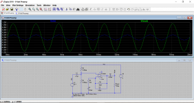
Here is the circuit in standard form and with 200mv peak applied followed by the same set up but now with a 100k feedback resistor.
The gain is calculated as G= (R4/R5) + 1
So for the 22k version we get (22000/22000) + 1 which equals 1. That agrees with the simulation. 0.2 in and 0.4 out.
And for the 100k we get (100000/22000) + 1 which equals 5.54. That to agrees. 0.2 volts in and we see 1.1 volts coming out.
Are you using a scope or an accurate DVM to measure the AC voltages ? A DVM may not be good at the very low levels involved and could give inaccurate results.
Attachments
@dotneck335, JMFahey, Mooly,
sorry for the format of my measuring values. I copied and pasted it from an excel sheet and it looked formated in the preview. So here again in text format:
R4 R4 / R5 Output OpAmp Output Preamp
22k 1 0.4V 35.8mV
50k 2.27 0.67V 59.1mV
130k 5.90 1.41V 126mV
250k 11.36 2.38V 216mV
500k 22.72 3.07V 279mV
(hope this is more readable)
And thanks for the many suggestions. Unfortunately there is no way changing the supply voltage because the whole preamp depends on the 9V.
@Mooly:
thanks again for your efforts. I'll have to recalculate my results. Seems that the 1st opamp stage is working allright then. So the new piezo seems to have a lot less output than the old one and I'll have to crank up input amplification to about 20 times the original value.
And yes, I'm using a standard DVM, so figure my values are not too accurate.
I'll try some more and will report my findings back here.
Yours
Rob
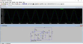
Here is the .asc file that should run straight off in LT IV or LTXVII
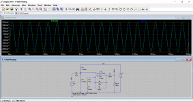
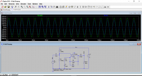
C2 provides additional feedback at HF. As the frequency rises, the caps reactance or Xc (its 'resistance' to AC) falls. That extra impedance appears in parallel to the feedback resistor and so has the effect of reducing gain.
For example, 150pf at 100kHz has a reactance of 10610 ohms. 10610 ohms in parallel with 22000 is 7158 ohms. So at 100kHz the feedback network is 'similar' to the equivalent of a 7158 ohm and the gain is reduced accordingly. Its not quite the same because the cap also introduces phase shift that complicates the calculations but you get the idea. Note the phase shift between the two diagrams below.
Attachments
It sounded dull. All mids, no bass, no treble. After trying out another preamp (Artec) with that piezo and not noticing any real change in sound, I decided that the pickup itself could be the problem.so what was wrong or bad about the original pickup?
The new fishman pickup sounds way better than the original Yamaha, but has significantly lower output. So I have to adapt the gain stage of the preamp, since I don't want to cut any new holes in my guitar for installing another preamp.
Yours
Rob
- Status
- This old topic is closed. If you want to reopen this topic, contact a moderator using the "Report Post" button.
- Home
- Live Sound
- Instruments and Amps
- Modification of old Yamaha piezo preamp for Fishman pickup - help needed