Re: Re: Thanks for all the research, guys!
I apologize for my bad English. I hope I did not offend anyone. I certainly did not mean to.
gallon said:
Xenu, I am lucky to know Steve Bench. He has a delightful sense of
humor. He would love the typographical error in your comments here.
")
I apologize for my bad English. I hope I did not offend anyone. I certainly did not mean to.
Re: Re: Re: Thanks for all the research, guys!
No offense is taken, do not worry. It is just good fun.
xenu said:
I apologize for my bad English. I hope I did not offend anyone. I certainly did not mean to.
No offense is taken, do not worry. It is just good fun.
Had anyone bulit the WEHE amp?
Had anyone (expect of course of Steve Bench) built this amplifier?
If so can you please share your experience?
Thanks
agent.5 said:http://www.intactaudio.com/forum/viewtopic.php?t=549
Is it the WEHE amp that you guys are talking about?
Had anyone (expect of course of Steve Bench) built this amplifier?
If so can you please share your experience?
Thanks
Lynn Olson said:
Hmmm - I'm pretty sure Steve is compensating for output stage distortion, not the drivers. Correcting the drivers is hardly worth doing, since it's the output stage that is the dominant source of distortion (in a well-designed amplifier).
...
That is probably true, but I can't seem to see how this works since it isn't sampling, from what i can see from the output of the output tubes.
JoshK said:
That is probably true, but I can't seem to see how this works since it isn't sampling, from what i can see from the output of the output tubes.
I would agree that the dominant source of distortion in a class A1
amplifier is the output device nonlinearity.
In a class A2 amplifier the grid drive can be a significant source;
in the case of 801A the Va vs. Vg is extremely linear and maybe
the grid drive nonlinearity would dominate.
In a push-pull amplifier, it's an oversimplification to say that the
device nonlinearity gets cancelled. Depending on the particular
topology and where the signal current loops are, first order non-
linearity is often converted into odd harmonic distortion.
The WEHE addresses this tendency. I believe Steve has applied
the principle to the task of correcting the odd series distortion
introduced by the finite impedance of the grid drivers and non-
linear current of the grid as first the grid is driven positive, then
as the anode voltage approaches the grid voltage in class A2.
Cheers,
Michael
PS It's inspiring to see it done entirely with vacuum tubes. A lesser
man such as I would have gone to MOSFETS long ago
Attachments
JoshK said:
That is probably true, but I can't seem to see how this works since it isn't sampling, from what i can see from the output of the output tubes.
WEHE is a specialized form of feedforward, not feedback. It "anticipates" a certain class of distortions and adds the inverse pre-distortion to the input or an interior node of the amplifier, without doing any output sampling at all. Feedforward is a standard technique in the RF world, where the transit delays of feedback cannot be tolerated in high frequency system.
Since the output (at the speaker level) is not sampled, there are no issues with phase margin, HF stability, sensitivity to reactive loads, or AM radio picked up on the speaker wires getting fed back to the input. These problems are more serious than generally acknowledged with feedback amplifiers, particularly reactive loads in the 20 kHz ~ 1 MHz region affecting the phase margin (and resulting TIM distortion) of the amplifier. Speakers and speaker wires are highly reactive at these frequencies.
To model the distortion of a Class A PP stage, think of a pair of center-tapped transformers - one an input transformer, the other an output transformer. The outer windings of the transformers are coupled by a pair of diodes. This is a full-wave rectifier, of course.
In reality, tubes are somewhere between the distortionless straight wire and this pair of balanced diodes. The transfer characteristics of the diodes is in fact the PP tube distortion, greatly exaggerated.
If we look at the current flowing between the center-tap of the input and output transformer, there's our distortion. If the tubes were distortionless, all that would flow would be biasing currents, or DC. There would be no audio-frequency content whatsoever. So all of the audio-frequency current flowing between the center-taps is distortion by definition. If the diodes are perfectly balanced, all of the distortion will be odd-order, with zero even-order content.
This distortion can be created with an external circuit as Steve Bench has done, and injected into a summing node that drives both halves of the circuit symmetrically. If the circuit is transformer-coupled as in the original WE circuit, it can be sampled at the center-tap, resistively divided as shown in the schematic, and re-injected at the center-tap of the interstage transformer. The WE approach isn't quite the same as conventional feedback, since it has no effect on the overall gain of the circuit at all - it only affects odd-order distortion.
Thinking this way may seem weird to us, but we have to remember the Bell System was working with accurately balanced transmission lines decades before the vacuum tube was invented. This was a requirement to minimize crosstalk between wire pairs on intercity links - which was why you had to shout into the telephone in the old days! It's also why the very first Bell System repeater amplifiers were balanced and transformer-coupled circuits - it was what the Bell System was already using and understood very well.
The phrase "line amp" originally meant telephone line amplifier, a repeater designed specifically for long-distance transmission on balanced circuits at audio frequencies. It wasn't until the Thirties and later that Bell gradually transitioned to RF modulation on coaxial cable, and in the Seventies to all-digital transmission on the same coaxial cables and microwave links, and then later to fiber-optic transmission.
Lynn Olson said:
WEHE is a specialized form of feedforward, not feedback. It "anticipates" a certain class of distortions and adds the inverse pre-distortion to the input or an interior node of the amplifier, without doing any output sampling at all. Feedforward is a standard technique in the RF world, where the transit delays of feedback cannot be tolerated in high frequency system.
Since the output (at the speaker level) is not sampled, there are no issues with phase margin, HF stability, sensitivity to reactive loads, or AM radio picked up on the speaker wires getting fed back to the input. These problems are more serious than generally acknowledged with feedback amplifiers, particularly reactive loads in the 20 kHz ~ 1 MHz region affecting the phase margin (and resulting TIM distortion) of the amplifier. Speakers and speaker wires are highly reactive at these frequencies.
Right! The polarity is wrong for it to be feedback to the drivers.
So it follows that the difference between + and - drive signals is fed
forward to both 801A grids -- The difference in + and - drive signals
arises from unequal grid current as one grid is driven positive.
The positive-driven grid draws current, resulting in less voltage
swing positive, which would result in a negative signal added
to both 801A grids. This would apparently cancel the 801A's
increasing gm as the grid is driven positive. Feedforward.
It seems too clever... But the damping factor of this is relatively
low with 8K anode-anode.
Thanks,
Michael
PS posts crossed, thanks for the deeper explanation; it all hangs
together
Attachments
Lynn Olson said:
WEHE is a specialized form of feedforward, not feedback. It "anticipates" a certain class of distortions and adds the inverse pre-distortion to the input or an interior node of the amplifier, without doing any output sampling at all. Feedforward is a standard technique in the RF world, where the transit delays of feedback cannot be tolerated in high frequency system.
Since the output (at the speaker level) is not sampled, there are no issues with phase margin, HF stability, sensitivity to reactive loads, or AM radio picked up on the speaker wires getting fed back to the input. These problems are more serious than generally acknowledged with feedback amplifiers, particularly reactive loads in the 20 kHz ~ 1 MHz region affecting the phase margin (and resulting TIM distortion) of the amplifier. Speakers and speaker wires are highly reactive at these frequencies.
I don't see pure harmonic distortion as a problem for music,
but it always goes hand in hand with IMD. With exception
for a single instrument where all sounds going into the IMD
are closely related (guitar) the hetrodyne products are not
generally musical.
Now, if you can anticipate a nonlinear event (such as clipping
upon voltage or slew rate limits) and preemptively add same
musically related harmonics that the non-linearity would have.
You move the signal peak away from any actual true clipping.
And the additive process need not be one that heterodynes
and generates IMD.
Something to chew on.
Sorry to bring back an old thread: is this the "harmonic signature" you are chasing for your amps?So, mine are not (I mean Pyramid-V and Pyramid-VII)... Below 1/8 of a max sinus power they generate 70 dB below the 2'nd order only, no others are visible, however above that power the 1'st pentode starts showing up the 3'rd and the 4'th... The driver and the output are both symmetrical so they can't show the 2'nd without the 3'rd. Are they not well designed?
Thanks
Been a while since I saw this thread.
The WE HE doesn't seem to have caught on at all obviously.
There are so many mis-understandings about WE HE, I think, because it was explained in the original papers using the frequency domain. Typical obtuse verbiage as found in patents, so no one would really understand and copy it.
A P-P stage, class A, with constant gm and no distortion, would have constant current from the OT CT to the B+. By monitoring that current in the real case, one sees the combined distortion currents of the output tubes as AC common mode current variation.
Now most power tubes have close to a square law Vg to Ip characteristic thru their central operating region. Which gives gm proportional to the SQRT of current or directly prop. to Vg. (similar to a Mosfet) The WE HE simply samples the common mode AC current and uses that to vary the common mode Vg (by adjusting common bias for the output tubes) to adjust the two tube's common mode gm. Unfortunately, the Fdbk signal needs to be square rooted to function linearly (gain wise) with grid V. One should do better by routing that feedback to a linearly variable CCS control ( modulated tail current under output cathodes).
This runs into problems of signal and adjustment range and loop gain unfortunately, since large variations in current are needed to adjust gm (gm prop. to SQRT Ip). Then there is the problem that a capacitor in the feedback path can also produce some phase shift or offset in the correction. (so WE HE is normally a common mode Neg Fdbk, much like used in many OP Amps internally today to linearize internal gain, except for bipolar devices gm is directly prop. to current ) In addition, the scheme is trying to maintain the same total gm as at idle, so power output may be limited.
Note that putting a CCS under the output tubes cathodes does not fix the problem either. Since the gm is non-linear with current, and the differential signal causes different currents in the two tubes. While the currents add up to a constant with the CCS, the gm's do not. The clever mechanism in the WE HE is that the gm modulation is being done in the same stage where the currents are split in the same ratio.
Getting more clever, one could try to move the gm modulation back to a class A driver stage, if the differential currents are split in the same ratio. (careful selection of DC bias current versus cathode size and feedback levels needed)
The scheme seems suited to a class A output stage, since class AB or class B would have the full differential signal showing up at the center tap. You only want the errors showing up as AC there.
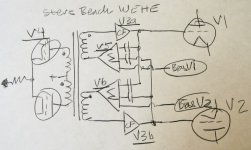
The Steve Bench HE is doing something quite different. The V5 and V8 followers are deriving the common mode portion in the output grid drive signals and feeding that back to the V3 drive followers as positive Fdbk.
Since T1 derives the two inverted grid drives, there is no common mode signal there. The only common mode source would be in the grid to cathode drops of the V3 drive followers. So maybe this has some effect for grid currents in the output tubes. But would seem to be making for more drop.
Maybe Steve can explain what is intended there.
------------------------------------------------------------------------------------------------------
On the original topic of new developments in tube amplifiers, I would say the real developments are Crazy Drive, which gives TV Sweep type tubes constant gm, a major breakthrough. Even class aB can operate as first order linear with that.
Then more recently, "new" series Schade (or CED, UnSET at Tubelab) have given us the ability to make high quality constant mu triodes (also the ability to adjust the amount of second harmonic if wanted). These triodes can be far better than the internal triode wired configuration previously available. The "shunt Schade" local N Fdbk schemes available before have an inherent flaw in the resistor derived N Fdbk, due to the low single stage gain allowing grid drive V to mix with N Feedback V in the Fdbk current derived in that resistor.
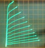
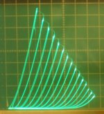
pics:
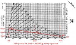
a) Crazy drive
b) "new" series Schade (CED, UnSET)
c) conventional grid 1 drive
d) conventional internal triode (note the curve "rollover" effect causing 2nd harmonic)
The WE HE doesn't seem to have caught on at all obviously.
There are so many mis-understandings about WE HE, I think, because it was explained in the original papers using the frequency domain. Typical obtuse verbiage as found in patents, so no one would really understand and copy it.
A P-P stage, class A, with constant gm and no distortion, would have constant current from the OT CT to the B+. By monitoring that current in the real case, one sees the combined distortion currents of the output tubes as AC common mode current variation.
Now most power tubes have close to a square law Vg to Ip characteristic thru their central operating region. Which gives gm proportional to the SQRT of current or directly prop. to Vg. (similar to a Mosfet) The WE HE simply samples the common mode AC current and uses that to vary the common mode Vg (by adjusting common bias for the output tubes) to adjust the two tube's common mode gm. Unfortunately, the Fdbk signal needs to be square rooted to function linearly (gain wise) with grid V. One should do better by routing that feedback to a linearly variable CCS control ( modulated tail current under output cathodes).
This runs into problems of signal and adjustment range and loop gain unfortunately, since large variations in current are needed to adjust gm (gm prop. to SQRT Ip). Then there is the problem that a capacitor in the feedback path can also produce some phase shift or offset in the correction. (so WE HE is normally a common mode Neg Fdbk, much like used in many OP Amps internally today to linearize internal gain, except for bipolar devices gm is directly prop. to current ) In addition, the scheme is trying to maintain the same total gm as at idle, so power output may be limited.
Note that putting a CCS under the output tubes cathodes does not fix the problem either. Since the gm is non-linear with current, and the differential signal causes different currents in the two tubes. While the currents add up to a constant with the CCS, the gm's do not. The clever mechanism in the WE HE is that the gm modulation is being done in the same stage where the currents are split in the same ratio.
Getting more clever, one could try to move the gm modulation back to a class A driver stage, if the differential currents are split in the same ratio. (careful selection of DC bias current versus cathode size and feedback levels needed)
The scheme seems suited to a class A output stage, since class AB or class B would have the full differential signal showing up at the center tap. You only want the errors showing up as AC there.
The Steve Bench HE is doing something quite different. The V5 and V8 followers are deriving the common mode portion in the output grid drive signals and feeding that back to the V3 drive followers as positive Fdbk.
Since T1 derives the two inverted grid drives, there is no common mode signal there. The only common mode source would be in the grid to cathode drops of the V3 drive followers. So maybe this has some effect for grid currents in the output tubes. But would seem to be making for more drop.
Maybe Steve can explain what is intended there.
------------------------------------------------------------------------------------------------------
On the original topic of new developments in tube amplifiers, I would say the real developments are Crazy Drive, which gives TV Sweep type tubes constant gm, a major breakthrough. Even class aB can operate as first order linear with that.
Then more recently, "new" series Schade (or CED, UnSET at Tubelab) have given us the ability to make high quality constant mu triodes (also the ability to adjust the amount of second harmonic if wanted). These triodes can be far better than the internal triode wired configuration previously available. The "shunt Schade" local N Fdbk schemes available before have an inherent flaw in the resistor derived N Fdbk, due to the low single stage gain allowing grid drive V to mix with N Feedback V in the Fdbk current derived in that resistor.
pics:
a) Crazy drive
b) "new" series Schade (CED, UnSET)
c) conventional grid 1 drive
d) conventional internal triode (note the curve "rollover" effect causing 2nd harmonic)
Attachments
Last edited:
On the original topic of new developments in tube amplifiers, I would say the real developments are Crazy Drive, which gives TV Sweep type tubes constant gm, a major breakthrough. Even class aB can operate as first order linear with that.
It seems like this would be more prone gm-doubling distortion like what happens in solid-state amps for the push-pull case. Wouldn't you have to take an approach where you find the ideal bias point for the smoothest gm handoff between sides to get lowest distortion? I always thought that the gradual change in gm in tubes was rather fortuitous as it allowed for a wide range of bias points to work well. I attempted to measure gm doubling distortion in a push-pull tube amp once and was unsuccessful. It was swamped by other distortion.
I remember reading Douglas Self's book where he shows that the handoff/overlap region is the largest source of irreducible distortion in a conventional class-AB solid-state amp. It would be interesting to repeat that work for a push-pull crazy-drive output stage and see if the same issues exist in a crazy drive amp and if the overlap region is as problematic as it is with solid state devices.
Another thing I'm noticing is that the crazy drive curves look an awful lot like high impedance transmitting triode curves. When I went from the 6384 beam tube to the 826 triode in my SE experiments I saw a substantial decrease in distortion even though I lost a lot of gain/gm for feedback in that swap.
As far Steve's HE circuit goes, it seems pretty complex for the performance it offers. It is super cool though.
Yes, constant gm down to zero current, like a bipolar trans, would have gm doubling issues. Crazy Drive does too if biased at the typical idle currents used for conventional tube P-P. However, Crazy Drive reverts to essentially grid 1 drive at relatively small current when grid 1 no longer carries grid current. I have seen someone demonstrate the gm doubling at conventional bias, and suggested they try low idle current. They never got back to report the results.
But there is no doubt that it must revert to grid 1 drive at low current, so should be overlap-able as well as normal grid 1 drive. (grid 1 gm is so much bigger than grid 2 gm when grid 1 is not loaded by grid current through the drive resistor.)
This is actually quite fortuitous, since the tubes can run efficiently near class B idle and constant gm above that.
Last edited:
Yeah, it looks really good. Has anyone built and measured a push-pull stage like this to see how well the transition works in practice?
It also looks like it would make a fabulous SE output stage with a little feedback to lower the Zout. I say that because those curves look a lot like the triodes I'm using and they are working very well for me.
It also looks like it would make a fabulous SE output stage with a little feedback to lower the Zout. I say that because those curves look a lot like the triodes I'm using and they are working very well for me.
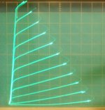
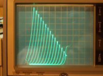
I have a setup here that takes the derivative (dV/dt) of a tube stage output signal when a triangle ramp is input to a stage. (has inverted signals for driving P-P stages too) It displays that derivative on a scope's vertical channel, while displaying the triangle ramp on the horizontal. A constant input ramp produces a constant dV/dt signal (DC) if the gain is constant across the trangle ramp input range. So effectively gain is displayed vertically versus input signal instantaneous level horizontally. A flat line (DC) display would indicate constant gain, and the scope's gain can be turned up to see even small gain variations.
This is the same as the "butterfly" gm or gain displays often published for SS Amps crossover (using an Audio Precision analyzer). I'll be checking Crazy Drive crossover with this when I get it back together. Right now it is scattered in pieces from a recent house move.
I believe this test method is a major visual tool for amplifier testing that has been missing for tube design. I already know the secret for linearizing an LTP stage from just a few tests. So much better than FFT testing. (for example, an FFT of a 2.0 power distortion versus a 2.01 power distortion give wildly different harmonic patterns, one has just a 2nd harmonic, and the other has a spray of higher harmonics. Yet they both sound the same. )
Last edited:
This is the same as the "butterfly" gm or gain displays often published for SS Amps crossover (using an Audio Precision analyzer). I'll be checking Crazy Drive crossover with this when I get it back together. Right now it is scattered in pieces from a recent house move.
I was thinking about the plots in Douglas Self's book earlier in this thread. I can't wait to see some similar plots for tubes!
D. Self 6th ed.
butterfly wing plots start on page 238, 239
lots of plots thru chaps. 9 and 10 and later for power Fets in chap,21, page 498
Not too hard to make a simple analyzer. Use a quality triangle or sawtooth generator for input signal. (constant rate ramps), adjusted for the input voltage range of the stage under test. Use an Op Amp inverter for P-P drive case. Triangle or Sawtooth Ramp signal goes to scope horizontal too. Then run the stage output (attenuate to safe level 1st) thru a differentiator (Op Amp with C input and R feedback, select C and R for freq. range of sawtooth, can put a tiny C across the R feedback also to take the sharp edges off the triangle or sawtooth, reduces noise too). Display the differentiator output signal on the Scope vertical channel. Adjust R and C for best display. Differentiators tend to make for a noisy output. Low pass filtering the Vertical signal, 4 or 5X above the triangle or sawtooth freq. can smooth out noise and leave the gain signal clean. Can check the triangle or sawtooth signal quality 1st by leaving out the stage under test (wire thru instead). Should give a nice flat gain display thru the wire. (opposite slope of trangle or sawtooth makes for a negative retrace)
Last edited:
- Status
- This old topic is closed. If you want to reopen this topic, contact a moderator using the "Report Post" button.
- Home
- Amplifiers
- Tubes / Valves
- Modern tube amplifier designs?