Eli Duttman said:
322ELC does not compute too. Forget the printing on the base. Tell us what is etched or printed on the glass envelope. I strongly suspect you will find 5U4GB.
You got it Eli. On the very top of the tube... there it is "5U4GB"

Mike,
There are at least 2 filament windings on the power trafo: 5 VAC for the 5U4 and 6.3 VAC for the signal tubes. Take a close look at the number of wires coming out of the power trafo. I want to know if more than one 6.3 VAC filament winding is present.
Are there any RCA jacks on the unit or was the signal I/P injected via that Octal socket umbilical connection? Separate connectors for the signal lines other than RCA are also a possibility.
Hey Eli,
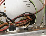
Here's a photo of the wires coming out of the power trafo. Is this adequate to get the answer to your question? I counted 11 wires coming out of the trafo on the amp itself.
The input came via the umbilical, but I've identified the input wires, so I can connect RCA jacks to them.
I've also got the power wires identified so I can install a switch and a fuse. Once I get the switch, fuse (3A FB?), and RCA jacks installed, I can use the amp totally independent of the tuner/control section. I was able to do this via some alligator clips and some wires the other night and it worked well.
Completing this is going to take a little longer than I had hoped. I found a pristine Pioneer SX950 yesterday that I couldn't pass up. There went my budget for my tube amp project for now. I'll keep working and researching, and I plan to get the parts in July.
So, in addition to caps, a switch, a fuse, RCA jacks, and a volume pot, I'd also like to beef up the OTs. Does this sound like I'm planning/heading in the right direction?
Thanks for your coaching effort on this project. I'm learning a lot.
Mike
Attachments
Mike,
That's an interesting photo. I see what appear to be some crappy RCA jacks, with phenolic insulation. Do those green wires connect to the small signal tube sockets?
It's necessary for you to trace out the power trafo connections. Two wires will connect to the 5U4's anodes. Two wires will connect to the 5U4's filament. At least 2 wires connect to the AC mains. At least 2 more wires will be associated with 6.3 VAC power. Possible, but unlikely, is a "universal" trafo with dual primaries.
Look at the 5U4GB data sheet. The basing diagram shows the under side of the socket.
If the convenience outlet is knocked out, a slide or rocker switch can be mounted in the opening.
Regardless of how power switching gets set up, its ABSOLUTELY mandatory to remove the OEM power cord and install a modern 3 wire cord, with its safety ground lead SECURELY bolted to the chassis.
Eli Duttman said:
Regardless of how power switching gets set up, its ABSOLUTELY mandatory to remove the OEM power cord and install a modern 3 wire cord, with its safety ground lead SECURELY bolted to the chassis.
Sounds good Eli. As far as a power cord; looking at a three prong plug, which spade should go to the trafo? I assume it would be the hot side, not the return, but I'd like to make sure of this. I've got an IEC jack and cord to use for this.
Does a 3 amp CB sound right?
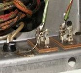
Those aren't RCA jacks, but I don't remember what plugged in to them. It appears they (eventually) go to OT's. I've attached a photo that shows one of them on the tuner, but it's the same as on the amp. It's on the far right in the picture. I've been able to find the point that the inputs come in from the umbilical, so I'll tie in there for my input connections.
Thanks,
Mike
Attachments
JJ (and others) make 500V multi-section electrolytic caps; here is a link to some at the tube depot.
http://www.tubedepot.com/can.html
http://www.tubedepot.com/can.html
Maybe those old phenolic insulated connectors are associated with power and represent something primitive along the lines of a Jones or Molex connector. A speaker connecter on the tuner does not make sense.
IMO, you should install a pair of isolated RCA jacks on the sheet metal and connect them to the voltage gain stuff via shielded "twinax" wire.
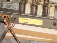
The tuner photo tells us that its chassis model # is 7TU12. Is there a similar sticker on the amp chassis? An amp model # could be a nice step towards obtaining the OEM schematic of interest.
IMO, you should install a pair of isolated RCA jacks on the sheet metal and connect them to the voltage gain stuff via shielded "twinax" wire.
The tuner photo tells us that its chassis model # is 7TU12. Is there a similar sticker on the amp chassis? An amp model # could be a nice step towards obtaining the OEM schematic of interest.
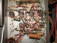
What 's the purpose of the orange cap?
Mike,
Perhaps it's a filter cap. for an O/P tube grid bias (negative) supply. Mounted on a terminal strip, it's physically far from the 4 "finals", which argues against it being part of a shared RC cathode bias network.
The importance of tracking down the OEM (Packard/Bell) schematic should now be obvious. We are making (at best) educated guesses.
Eli Duttman said:The importance of tracking down the OEM (Packard/Bell) schematic should now be obvious. We are making (at best) educated guesses.
Or just tracing the schema... i learned a huge amount doing that.
dave
I got it wired up tonight to run independently of the tuner/control section. I got rid of the old power cord and installed a cord with a ground, installed an inline fuse, and wired in some RCA jacks and speaker terminals. Once I get a case built for it, I'll tidy it up and install a power switch. I'll order new caps for it next month.
I ran it directly from my computer for a while and it sounded darned pretty good, especially considering I've only spent a total of about $35 for it.
I'd like to possibly replace the OT's, but that'll have to wait for a while. I'd like to run it with the current OT's after a recap and see how it sounds.
Mike
- Status
- This old topic is closed. If you want to reopen this topic, contact a moderator using the "Report Post" button.
- Home
- Amplifiers
- Tubes / Valves
- Modding an old tube amp???