The only commercial amp I'm aware of that comes close (and beats on a few specs) the MOD86 and MOD286 is the Benchmark ABH-2. It's $3k (USD). I'll openly admit that I haven't completed an exhaustive search, but I don't see any products out there with THD below -120 dB and the IMD, etc. that follows.
Tom
Tom
The only commercial amp I'm aware of that comes close (and beats on a few specs) the MOD86 and MOD286 is the Benchmark ABH-2. It's $3k (USD). I'll openly admit that I haven't completed an exhaustive search, but I don't see any products out there with THD below -120 dB and the IMD, etc. that follows.
Tom
Yes that confirms what I found on my quick check and most manufactures don't even offer such an extensive set of data. Most show THD, some THD+N, some SNR, some damping.... but I have not come across one who gives the transparency about IMD, slew rate, IMD etc. you provide
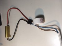
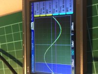
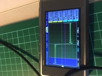
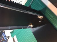
Tonight I tried to conduct that test, that Andrew suggested and Tom described in post #55. I ran a 500Hz sine and (almost) square wave into both of my Mod286s with an 8ohm resistive load and a 1.5uF capacitive load attached.
Because of the small heat sink I only went up to ca. 1.8W max. (Ca. 11Vpp out). Most of the tests I ran only at a fraction of that ca 2Vpp output. The purpose was to reconfirm that both boards are putting out power equally and to reconfirm the 20dB (10x).
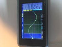
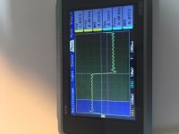
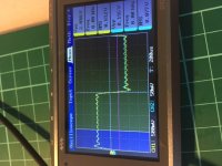
Both went well in my eyes given the inadequate oscilloscope and the poor square wave generation. The square wave input isn't really a "snappy" square wave and has already oscillations which the output also reflects then. The oscilloscope div/V setting for the input and output channel are set to differ by a factor of 10. Therefore the lines are (about) identical. Every other difference I would put down to the poor oscilloscope.
Please comment if you have any hints.
Because of the small heat sink I only went up to ca. 1.8W max. (Ca. 11Vpp out). Most of the tests I ran only at a fraction of that ca 2Vpp output. The purpose was to reconfirm that both boards are putting out power equally and to reconfirm the 20dB (10x).
Both went well in my eyes given the inadequate oscilloscope and the poor square wave generation. The square wave input isn't really a "snappy" square wave and has already oscillations which the output also reflects then. The oscilloscope div/V setting for the input and output channel are set to differ by a factor of 10. Therefore the lines are (about) identical. Every other difference I would put down to the poor oscilloscope.
Please comment if you have any hints.
Attachments
Last edited:
It looks to me like the amp is providing exactly 10x the input voltage. Your input (blue trace) is pretty dirty and has quite a bit of ringing and noise on it - as you point out - so the output will reflect this.
If you're using a sound card as the signal generator, maybe this is the best it can do. If you're using an actual signal generator, I suggest adding termination to the input cable right where it goes into the amp. If your signal generator has 50 Ω out, I'd terminate the amp input (from pin 2 to 3 on the input connector) in 50 Ω (49.9 Ω is the nearest standard 1 % value).
Tom
Thanks Tom. For signal generation I used even worse than a sound card... I used an app on my smart phone so no wonder. The signal generator which is built into the oscilloscope delivers a cleaner signal but came with an offset, meaning the lowest peak of a signal was 0V and everything else >0. However I didn't terminate that signal with the suggested 50ohm, maybe that fixes it. I will try that the next few days.
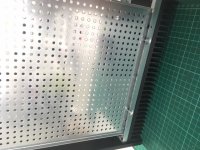
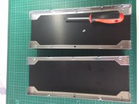
Yesterday the housings came from Modushopbiz - yeah and today was a bit of a rainy day outside - so good weather to start with the assembly. The two Dissipante 3U/300 with alu fronts and covers arrived perfectly packed and in perfect condition and are really nicely made. Only the attached assembly manual isn't as straightforward as it could be. As there are more types of screws packed together with each housing as there are necessary (most likely for other versions) one needs to give it some thought which screw goes where. See the photos for how I have done it. The bottom and top covers go on using the self tapping screws. The rest are M4 machine screws and nuts.
Attachments
Last edited:
Dont want to threadjack here.... but....
I too am working on a build and was wondering what are the advantages/disadvantages of using sockets for the opamps?
And if not using sockets should I leave a little space when soldering the leads or butt them right against the pcb?
TIA
I too am working on a build and was wondering what are the advantages/disadvantages of using sockets for the opamps?
And if not using sockets should I leave a little space when soldering the leads or butt them right against the pcb?
TIA
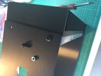
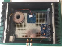
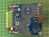
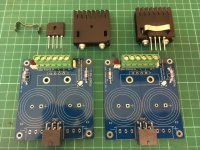
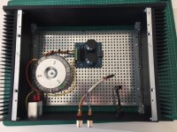
Also I have laid out the components roughly as they should go in before tapping the threads for the Mod286 attachment to the heat sinks. (The components for the Power86 boards should arrive tomorrow).
What do you guys think about the layout? Is it ok or should I move any component elsewhere? For instance, would the trafo right next to the mains inlet be a better choice?
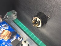
Secondly I have read in the Mod286 manual that the XLR pin 1 should be connected to the housing of the XLR inlet (see the little solder point next to pin 1). The XLR housing also has a connection via its metal housing to the backplate of the amp housing. Which in turn will have to be connected to the protective earth.
Is the connection via the backplate sufficient or should I run a seperate copper wire from the XLR housing solder point to the protective earth?
Thx
What do you guys think about the layout? Is it ok or should I move any component elsewhere? For instance, would the trafo right next to the mains inlet be a better choice?
Secondly I have read in the Mod286 manual that the XLR pin 1 should be connected to the housing of the XLR inlet (see the little solder point next to pin 1). The XLR housing also has a connection via its metal housing to the backplate of the amp housing. Which in turn will have to be connected to the protective earth.
Is the connection via the backplate sufficient or should I run a seperate copper wire from the XLR housing solder point to the protective earth?
Thx
Attachments
Last edited:
I too am working on a build and was wondering what are the advantages/disadvantages of using sockets for the opamps?
The Modulus-286, which is what this thread is about, does not have any socketed opamps. They're all surface mounted.
Tom
What do you guys think about the layout? Is it ok or should I move any component elsewhere? For instance, would the trafo right next to the mains inlet be a better choice?
I'd keep the wiring from the transformer to a minimum. Also keep the wiring to the Power-86 to a minimum. So I'd scoot the transformer closer to the IEC inlet and rotate the Power-86 90º. These wires should be tightly coupled - so bundle with zip ties.
Is the connection via the backplate sufficient or should I run a seperate copper wire from the XLR housing solder point to the protective earth?
The metal of the XLR connector should make good electrical contact with the back plate. You may have to remove any coating under the connector to make that happen. As long as the XLR is connected electrically to the chassis through its mounting flange, you're good. Connecting the XLR flange to the chassis is necessary if you want the best RF immunity. A wire connection to the chassis won't help much with that. I wouldn't obsess too much about this as RFI isn't usually a big issue for residential applications.
Tom
To get the best RFI immunity you'd need to move all five components of the RFI filter to the XLR connector. You'd also need to ensure a good electrical connection between the chassis and the connector. To further improve on the RFI immunity, switch the XLR to one of the Neutrik EMC series.
Now you do all that and you find you have more RF leaking through various openings and seams in the chassis. So you'd have to add more screws (about one every 2 cm is typical, depending on the wavelength you need to keep out). You'd also use an RF gasket (metal mesh that's crushed in the gap between two chassis plates. You'd have to weld up all ventilation holes. All wires into and out of the box will need to go through a filter and feed-thru cap. This includes the speaker wires. You'd have to do something to seal the hole for the power switch such that RF couldn't enter there. If you want to see what that looks like, have a look at satellite avionics.
As I've said before, a little perspective is appropriate. Which is why I've kept the filter on the board. While you can certainly geek out further on the RFI immunity, the solution that's there works well and is convenient to work with.
Tom
Last edited:
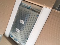
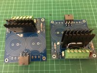
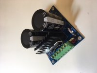
Today the parts from Mouser arrived for the two Power86 power supply boards. I put them together quickly and they tested out a ok. No problem and easy to follow documentation.
Next is the mechanical mounting of all the components inside the new housings.
Next is the mechanical mounting of all the components inside the new housings.
Attachments
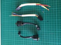
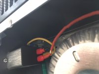
Finally the new trafos 2x25Vac, 300VA came in, replacing the previously used 2x22Vac, 160VA ones. Time to wire it all up. See below pics showing the XLR ins, the speaker wires, a view of the mains inlet with the PE attached to the housing and an overall view of the amp without the Mod286 being in place.
Please give hints on my wiring scheme so I can improve it before I box it all up.
Thx
Please give hints on my wiring scheme so I can improve it before I box it all up.
Thx
Attachments
Actually, Andrew, the terms "biamping", "triamping", etc., have been in common use in the USA for at least 40 years (especially in pro audio circles where it began) to refer to what you are calling an "active loudspeaker" -- a system with a line-level crossover that separates the incoming signal into band-limited signals to drive separate amplifiers that drive each particular driver (woofer, mid, tweeter, etc.)
Though not common, 'high end' speakers were 'biamplified' and 'triamplified" even in the early '70s. Bozak sold at least one crossover for biamping their Concert Grand and Symphony systems, one amp to the woofer and the other amp to the mid/tweeter (passive LC between them). The Magnepan Tympany IIIa was biamped with a separate amp driving the low frequency panels and another amp doing the mid/tweet panels; those really in the know had a 3-way line-level crossover and separate amps for each. Audio Research sold a number of crossovers for the various early Magneplanar systems. Google will lead you to documentation for a number of these crossovers and you can see that the terms 'biamping' (or 'bi-amping') and triamping were used in the way I described.
From what I have observed, the term "active loudspeaker" generally refers to a system where all the electronics are integrated into the speaker 'box' (mains voltage and line-level (or digital) in --- sound out). The earliest example I know of was a Philips speaker that these days would be classified as a 'mini-monitor' similar in size to a BBC LS3/5. Where you draw the terminology line of demarcation between a fully integrated box and the same stuff with electronics in a separate box(es).
The confusion began when people in high end audio started using the term "biamping" to refer to the odd practice of using two full-range amplifiers to drive one speaker whose passive speaker-level crossover could be separated into low-pass and high-pass sections, each with their own terminals. Unfortunately the audiophile world knew little of the original, correct, use of the term which had been in common use in the audio workd for decades at that point; hence the confusion. Those trying to be less confusing tend to refer to this as "passive biamping".
Don't sell the "audiophile world" so short. We (that is, myself and those around me) were Bi-Amping QUAD ESLs and Subs (which, in those days, often didn't come with built-in amps and crossovers), Tri-Amping Decca Ribbon Tweeters, single or dual QUAD ESLs and Subs, Bi-Amping Dayton-Wright XG8's and Subs, and of course, there were the big Infinity setups. We mostly used the Nakamichi electronic crossovers and Bryston power (QUAD 405s for the ESLs) often in Mono configuration as they were super stable into reactive loads (4B = 2x 200w or 1x 800w 8ohms). (The Dayton-Wrights cost us a few bucks, turning many vaunted Power Amps into boat anchors. Some of the big Infinity's weren't far behind. Not with the Brystons).
There were others electronic Xors available in the Pro Audio world. We're talking late 1970's here.
The biggest subs we ever built had 2x 18" drivers in sealed boxes, and yeah, we ran them in stereo. M&K (Miller & Kreisel) were making commercial self-powered subs by then.
There is no practical difference between using electronic crossovers or passive crossovers with multiple amplifiers. They are both examples of Bi- or Tri- amping. And yes, they are distinct from Powered Monitors, regardless of how many or how configured the internal amps are.
Nakamichi EC-100
Last edited:
Please give hints on my wiring scheme so I can improve it before I box it all up.
Looks good to me.
Tom
Thanks. I wasn't sure about my implementation of the earthing scheme. I now run the yellow wire from the PSU back to the PE of the mains inlet. Alternatively one could have connected the PSU GND directly with a short wire to the metal bottom plate which in turn is also connected to PE. Basically these were the two alternatives of which I chose the first but wasn't entirely sure if that is the correct / best one.
Thanks. I wasn't sure about my implementation of the earthing scheme. I now run the yellow wire from the PSU back to the PE of the mains inlet.
That's how you want it.
I prefer green or green+yellow stripe wire for the grounding connection as that's normally what's used in power cords and household wiring. I'm not suggesting that you change anything, just adding information for use in future projects.
Alternatively one could have connected the PSU GND directly with a short wire to the metal bottom plate which in turn is also connected to PE. Basically these were the two alternatives of which I chose the first but wasn't entirely sure if that is the correct / best one.
You implemented it correctly. You do not want to rely on the chassis for electrical connections between point A and point B. Think about how many interfaces that can fail and screws that can rattle loose or corrode in that connection. The chassis should be grounded and that's it.
Tom
- Status
- This old topic is closed. If you want to reopen this topic, contact a moderator using the "Report Post" button.
- Home
- Amplifiers
- Chip Amps
- Mod-286 build thread