Banned
Joined 2002
Banned
Joined 2002
Cal Weldon said:Good to hear. What do you think of them?
Cal
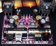
Well they look like boards
 now to get the parts to use them ..
Translate from designer:
1.First I like to thank the senior designer Per-Anders' suggestions.
Each unique designer has his need, goal with different thoughts or subjective point of view.
Mini Regulator is good both in testing and listening, with the parts in partlist interacting with the board's layout.
2.As for layout of the PCB, designer had evaluated and tested.
If there's any modification that will really improve the listening feeling, I will update the modification.
I think the influence and improvement of listening will be the prime thing for most audiophiles.
Persons who applied the sample, please build it with the partlist provided by designer to make sure the reg works properly.
If after listening to the mini reg in your system, you are still not satified, please post on this thread.
Please specify your equipments, your system(including source/amp/speaker and brand name), and your listening space. It will be helpful for designer to get information to improve the reg.
3.Q2 and Q3 are not current mirror. they are an usual temperature-stabled current source.
4.The part list and schematic are open to everyone if there's no any commercial usage.
5.Mini Reg is one stage regulator, without any pre-regulation.
If you want to get better result, You can use 2 pieces of Mini reg to form a 2-stage regulator. The effect will be positive.
cheers
Coffin
transistor & opamp substitutions
For a dual high voltage version (+/-75v) I want to make, is there any reason why the OPA445 is the only choice? It's a very expensive part ($9.50 at Digi-key).
And Q1/11 are hard to find--I was thinking of complementary matched MJE4343 and MJE 4353. Maybe even MJE 15030 & 15031. They should all work....
Hi
For Q1/Q11, you can use other audio power transistor if their rating are right. Do not use Darlington transistor.
2SK170GR can be replaced by any n-channel Jfet with 3-8mA Idss. But watch out the pinout.
For +/-75V, OPA445 has high voltage rating and cannot be replaced.
cheers
Coffin
For Q1/Q11, you can use other audio power transistor if their rating are right. Do not use Darlington transistor.
2SK170GR can be replaced by any n-channel Jfet with 3-8mA Idss. But watch out the pinout.
For +/-75V, OPA445 has high voltage rating and cannot be replaced.
cheers
Coffin
It's apparently easier to order a free board than to actually do something with it once you have it Mine arrived last week looking all sexy and ready for action.
Now, i've known about Jung's circuit since the time i was subscribed to AA and never felt a serious compulsion to do anything about it. Don't ask me why - it's more than 20 years ago and i've largely forgotten.
Anyway, followed Coffin's instructions and used all the prescribed transistor types, MUR860 and a bit lower filtering capacitance as the current draw is very modest.
Having read about Per Ander's experience with the board i cautiously installed a couple of vintage 5534s into the sockets. Input DC was 20v for 12v output.
200mA load; no oscillations. Getting more brave i tried a 627. Still fine. Similarly stable at currents between 0-200mA were AD8610, AD8065, AD825, OPA637.
An AD797, otoh, drove the regulator wild. If i really wanted to know i could have removed the 100nF smd at output and tried a few tricks to calm it down but do i really need a 797 based regulator?
In the listening tests i used the +- 12v to feed a simple opamp based phono stage which was previously powered from a very nice discrete circuit. 627s were used.
After giving the BGs a chance to settle down a bit i gave it a listen. Very, very nice indeed. A lot more detail and precision compared to my discrete reg and all this without sounding artificial.
Briefly tried the AD825 but it didn't work too well - the sound lost liquidity and became a bit strained.
Many thanks to Coffin for graciously providing the sample boards.
Mine arrived last week looking all sexy and ready for action. Now, i've known about Jung's circuit since the time i was subscribed to AA and never felt a serious compulsion to do anything about it. Don't ask me why - it's more than 20 years ago and i've largely forgotten.
Anyway, followed Coffin's instructions and used all the prescribed transistor types, MUR860 and a bit lower filtering capacitance as the current draw is very modest.
Having read about Per Ander's experience with the board i cautiously installed a couple of vintage 5534s into the sockets. Input DC was 20v for 12v output.
200mA load; no oscillations. Getting more brave i tried a 627. Still fine. Similarly stable at currents between 0-200mA were AD8610, AD8065, AD825, OPA637.
An AD797, otoh, drove the regulator wild. If i really wanted to know i could have removed the 100nF smd at output and tried a few tricks to calm it down but do i really need a 797 based regulator?
In the listening tests i used the +- 12v to feed a simple opamp based phono stage which was previously powered from a very nice discrete circuit. 627s were used.
After giving the BGs a chance to settle down a bit i gave it a listen. Very, very nice indeed. A lot more detail and precision compared to my discrete reg and all this without sounding artificial.
Briefly tried the AD825 but it didn't work too well - the sound lost liquidity and became a bit strained.
Many thanks to Coffin for graciously providing the sample boards.
Attachments

other parts substitutes
Coffin,
After looking more closely, I was wondering if 2) LM329 6.9v precision zener diodes (in series for 13.8v) could be used at IC1/2 instead of the 15v 1/2W zener (this is for +/-75v).
R1/2 can easily be adjusted slighty to get to 75v. My concern is proper power/current rating for 2 of these in series.
Any thoughts?
Re: other parts substitutes
Hi
IC1.IC2= LM329 6.9V ( ONLY ONE )
R1=29.6K 0.5W or 0.6W
R2=3K 0.5W or 0.6W
cheers
Coffin
izzyman said:Coffin,
After looking more closely, I was wondering if 2) LM329 6.9v precision zener diodes (in series for 13.8v) could be used at IC1/2 instead of the 15v 1/2W zener (this is for +/-75v).
R1/2 can easily be adjusted slighty to get to 75v. My concern is proper power/current rating for 2 of these in series.
Any thoughts?
Hi
IC1.IC2= LM329 6.9V ( ONLY ONE )
R1=29.6K 0.5W or 0.6W
R2=3K 0.5W or 0.6W
cheers
Coffin
wrong voltage: 40v out, not 75!
Coffin,
I used the LM329 6.9v zener and R1/2 values of 28.5k/2.9k which should give me +/-75 v out. But I get +/- 40.5 v out!
From BOTH plus & minus rails, this is too much of a coincidence. It almost seems like the 39v of ZD1 prevents any more V out. I first turned it all on with a variac, and got fine results until Vin got over 45v: then I kept increasing it but Vout stayed at 40!
Any idea what's wrong & how to fix?
-izzy
parts list
Q1: MJE15030
Q11: MJE 15031
D1,2,5,11,12,15: 1n4004 (a lower voltage rating than the insanely high 1000v rating of the 4007)
C6,16: 22uF/50v
C7,17: 30pF
Sure, I'll only list the changes/substitutions I made (aside from what I already listed--the LM329 & R1/2 change):coffin said:Hi
Can you prcisely list all the parts value you use?
cheers
Coffin
Q1: MJE15030
Q11: MJE 15031
D1,2,5,11,12,15: 1n4004 (a lower voltage rating than the insanely high 1000v rating of the 4007)
C6,16: 22uF/50v
C7,17: 30pF
wrong voltage: 40v out, not 75!
DUH! I feel dumb--I inadvertantly swapped R1 & R2!!
I corrected it, and now I have too MUCH voltage! 82V out (84 in), and the LED's are blown. But ripple is low on one rail (10mv AC) and moderate on the other (140mv)
Hopefully nothing else is damaged. Will replace the LED's and see what happens.
DUH! I feel dumb--I inadvertantly swapped R1 & R2!!
I corrected it, and now I have too MUCH voltage! 82V out (84 in), and the LED's are blown. But ripple is low on one rail (10mv AC) and moderate on the other (140mv)
Hopefully nothing else is damaged. Will replace the LED's and see what happens.
- Status
- This old topic is closed. If you want to reopen this topic, contact a moderator using the "Report Post" button.
- Home
- Amplifiers
- Power Supplies
- Mmini regulator (sample offering)