If the tubes are used in a push-pull output stage arrangement, matching is preferred, but not really mandatory, so long as both tubes are in reasonably good condition. I'm not familiar with the Fender amp, but if it has bias adjustments, then matching is less important; what you don't want is one tube hogging current while the other is near cutoff. This would cause a steady magnetization of the output transformer's core, an undesirable condition. If the output stage is self-biased; that is, it uses a common cathode resistor for both tubes, then matching is a better way to go, to ensure that the tubes share the DC quiescent current. You don't want one tube red-plating while the other one is in cutoff. If the tubes are used in parallel in a single ended arrangement, then matching would be less important.
in a guitar amp mismatched output tubes are often preferred. It improves the tone. Uncle Doug talks about this in a bunch of his videos. https://www.youtube.com/@UncleDoug
The worse the amp, the better they like it.Guitar amps aren't meant for high fidelity, so anything goes.
So I take it the second tube in the output only serves as a fixed current sink?
Dont some designs simply wrap the secondary back around to drive the "opposing" tube? One would think a "3rd harmonic" control would be a feature, by driving the otherwise quiescent tube at least some via a potentiometer connected to the secondary.

Dont some designs simply wrap the secondary back around to drive the "opposing" tube? One would think a "3rd harmonic" control would be a feature, by driving the otherwise quiescent tube at least some via a potentiometer connected to the secondary.
The other side is driven by the voltage changes across Rk. So somewhat PP.So I take it the second tube in the output only serves as a fixed current sink
This circuit has been making the rounds since before WW2. This one from WW2
when there were shortages of many kinds.
Attachments
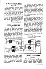
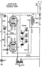
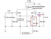
The Sparton 8549 BC Receiver uses a self inverting stage with PP 6V6s to drive the loudspeaker.
A common application of this kind of circuit, the marketing department could now boast PP output.
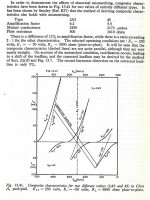
In this example. the inversion is far from perfect for the lower 6V6 in the schematic..
The relation ( mu + 1 ) Rk >> rp + Rl, where Rk is the cathode resister & mu for the tubes.
Try that math on a Mullard long tailed pair, it looks much better.
Several years ago I tried several versions of this circuit. The best results were got
with a Choke as a cathode tail. All the results are here somewhere in DIY.")
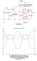
A common application of this kind of circuit, the marketing department could now boast PP output.
In this example. the inversion is far from perfect for the lower 6V6 in the schematic..
The relation ( mu + 1 ) Rk >> rp + Rl, where Rk is the cathode resister & mu for the tubes.
Try that math on a Mullard long tailed pair, it looks much better.
Several years ago I tried several versions of this circuit. The best results were got
with a Choke as a cathode tail. All the results are here somewhere in DIY.
Attachments
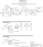
I suspect that the rationale for using a choke for a plate load impedance is to lower DC resistance. The voltage drop from the DCR greatly reduced, and a lower voltage supply could be used. Resistor thermal noise would also be lowered. For me, chokes live only in my power supplies. You know, I think that chokes are devices that treat electricity cruelly. They make the stuff go round and round so many times through those windings that it comes out so dizzy that it can't even keep its voltage and current in step. What did 'lectric ever do to deserve such awful treatment?
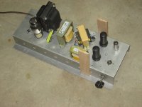
The choke in this series of tests was always in the tail of the PP cathodes.
Many other tests with resistors, NFETs, BPT & 3-term regulators were tried
The tests are all real. no simulations. The test mule is a simple PP 6V6s driven
by a triode connected 6AU6. Lots of results, a few of which are here.
As a way to build an amp, it gets my thumbs down.
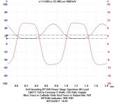
Many other tests with resistors, NFETs, BPT & 3-term regulators were tried
The tests are all real. no simulations. The test mule is a simple PP 6V6s driven
by a triode connected 6AU6. Lots of results, a few of which are here.
As a way to build an amp, it gets my thumbs down.
Attachments
-
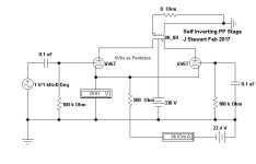 500R Tail to -22.4 Volts Self Inverting PP Stage.jpg31.5 KB · Views: 10
 -
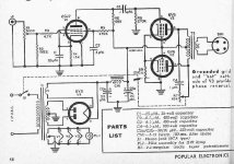 250R to Common Self Inverting Amplifier Popular Electronics.jpg51 KB · Views: 10
 -
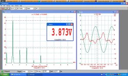 5H Choke Tail One Watt.JPG152.6 KB · Views: 10
 -
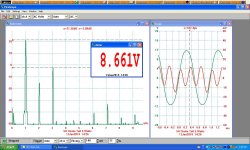 5H Choke Tail 5 Watts.JPG154.9 KB · Views: 11
 -
 5H 255R to Common Tailed Self Inverting PP Stage..jpg34.3 KB · Views: 9
 -
 5H 255R to Common Tailed Self Inverting PP Stage. with Cathode Trace.jpg104.8 KB · Views: 9
 -
 IMG_2081.JPG404.8 KB · Views: 9
 -
 2017_02_02_001 Self Inverting Stage 5 Watts Cathode Trace.jpg42.6 KB · Views: 10
- Home
- Amplifiers
- Tubes / Valves
- Mixed power tubes in a guitar amp?